
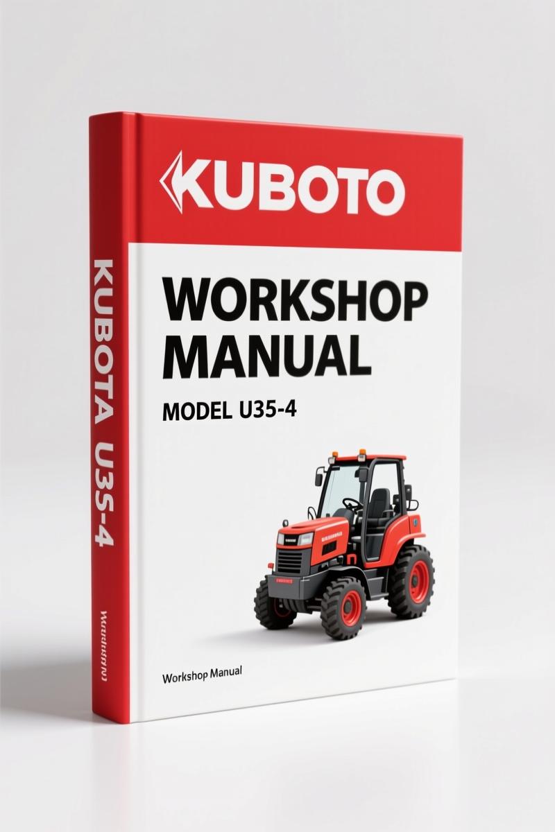
Kubota U35-4 2013 Workshop Manual — Factory Specs for Mini Excavator
Original price was: $89.05.$65.00Current price is: $65.00.
Factory Kubota U35-4 2013 Workshop Manual: 514 pages of torque specs, hydraulic diagrams, and engine overhaul procedures for certified technicians.
Description
Kubota U35-4 2013 Workshop Manual
If you are holding this manual in your hands, you have already figured out that the aftermarket PDFs floating around won’t cut it. I have seen more than a few guys snap a hydraulic line fitting because they guessed the torque on a 3/8-24 adapter. This Kubota U35-4 2013 Workshop Manual is the OEM factory print – 514 pages of the exact specs Kubota used on the assembly line. I have torqued more head bolts than most people have had hot meals, and I can tell you: without the factory torque table on page G-14, you are playing roulette with every fastener. The manual covers the 2013 model year U35-4 mini-excavator, and it includes everything from safety labels to hydraulic circuit diagrams. No reprints, no third-party guesswork.
Tightening Torques: The Section That Saves Your Threads
Every bolt on this machine has a spec. Page G-14 lists tightening torques for general use screws, bolts, nuts, stud bolts, hydraulic hose fittings, lock-nuts for elbows with male seats and adaptors with O-rings, and hose clamp screw torque. You get both Nm and foot-pound values. I have seen guys use a calibrated wrench and still get it wrong because they referenced a generic chart. This manual gives you the right torque for M6 through M20 fasteners in the exact application. Do not skip this section.
7 Main Sections in the Machine Body Chapter
The Machine Body chapter splits into three major servicing groups: Front Equipment (beginning 1-S1), Upper Swivel (1-S12), and Track Frame (1-S33). Under Front Equipment you get the arm assembly/disassembly, boom assembly, bucket installation joint dimensions, front pin dimensions, blade disassembly. The Upper Swivel section covers the weight, canopy, fuel tank, hydraulic oil tank, engine, and operating lever/pedal. Track Frame includes swivel bearing, crawler (rubber and iron track assembly), front idler, spring assy, cylinder assy, track roller, and carrier roller. Each subsection has its own component diagrams and step-by-step disassembly procedures. If you need to replace a track roller, the manual shows you the mounting torque and structural components.
How the Hydraulic Circuit Diagrams Are Organized
Hydraulic system work is where most people get lost. The manual dedicates the entire Chapter 3 to the hydraulic system, starting with a diagram of the hydraulic circuit on page 3-M1. There are two diagrams: one for the canopy version with angle blade option, one for the cab version. After that you get hydraulic device layout, pump specifications (page 3-M3), control valve (3-M10), swivel motor (3-M17), travel motor (3-M22), hydraulic cylinder (3-M30), pilot valve (3-M37), unload valve (3-M45), plus auxiliary solenoid valves and proportional valves for angle blade and AC mode control. The servicing section (3-S1) goes into pump disassembly, control valve rebuild, swivel joint, travel motor overhaul, and hydraulic cylinder tear-down. Want to measure the performance of hydraulic devices? That is covered too.
Engine Identification and Serial Number Location
Before you pull the engine, you need to confirm you have the right model. Page G-2 shows the engine identification section, including the model name and serial number for the E4B engine and cylinder numbering. The manual also lists engine specifications on page 2-G1, external dimensions on 2-G2, and a performance curve on 2-G3. If you are swapping an engine or ordering parts, that serial number is critical. The manual walks you through checking excavator identification first (page G-1) so you match the right manuals.
Safety Instructions Before You Touch the Mini-Excavator
Page I-1 starts with “Safety First”, and page I-2 goes into “In the Interest of Work Safety” – Precautions Before Working on the Mini-Excavator, and Precautions Before Working on the Equipment. The manual also details labels displayed to promote work safety, their locations, and label maintenance. If you are working in a shop that deals with liability, having the OEM safety information on hand is non-negotiable. The General Precautions section (page G-5) covers handling precautions for electrical parts and wiring, including fuses, connectors, and even washing the machine with a high-pressure washer. Read that before you hose down the engine bay.
Why OEM Documentation Beats Aftermarket Copies
I have chased down wiring pinouts in third-party manuals that were dead wrong. This Kubota U35-4 workshop manual was issued by Kubota in March 2013 – KISC release A. The table of contents matches the actual bookmarks inside the PDF. You get the full 514 pages, not a condensed version. Aftermarket manuals often leave out the exact torque for hydraulic hose fittings or the correct sequence for arm assembly. Here, every section is complete, from the machine body servicing to the hydraulic system mechanism. If you need a related manual for another machine, check the Kubota U35-4 2013 Operators Manual – Factory Excavator Specs for daily operation or the Kubota R420B R520B Workshop Manual – Factory Specs for Wheel Loaders for wheel loaders. For older engines, the Kubota Z402-EB 2000 Workshop Manual – Factory Service Specs is also available.
Understanding how a Manual Transmission works helps when diagnosing the travel motor reduction gears in this machine. The swivel motor also contains gears similar to a Manual Transmission. But for the Kubota U35-4, the manual gives you the factory data, not approximations.
Frequently Asked Questions
- What model years does this manual cover?
- 2013 model year U35-4 only.
- Does the manual include wiring diagrams?
- No, this workshop manual focuses on mechanical and hydraulic systems. Electrical wiring is mentioned only in the handling precautions section on page G-9, where it covers fuses, connectors, and high-pressure washing precautions. For full electrical schematics you need the separate wiring diagram manual that Kubota publishes for the U35-4. That manual is not included here. The hydraulic circuit diagrams on page 3-M1 are complete, but they are not electrical schematics.
- Can this manual be used for a U35-4 with a cab?
- Yes, the manual covers both canopy and cab versions. The hydraulic circuit diagrams include both configurations on pages 3-M1 and 3-M2. The upper swivel section also contains canopy and cab assembly/disassembly steps.
- How many pages is the manual?
- 514 pages.
Stop working from photocopied scraps. Access the Factory Manual and get the real specs that Kubota engineers put into this machine. No guesswork, no stripped threads, no wasted time.
Additional information
| Brand | Kubota |
|---|---|
| Language | English |
2 reviews for Kubota U35-4 2013 Workshop Manual — Factory Specs for Mini Excavator
You may also like…
-
Sale!
Kubota KX36-3, KX41-3S, KX41-3V Workshop Manual – OEM Service Data
Original price was: $101.40.$65.00Current price is: $65.00. -
Sale!
Kubota KX91-3, KX101-3 Workshop Manual – 610 Pages
Original price was: $100.75.$65.00Current price is: $65.00. -
Sale!
Kubota KX057-4, U55, U55-4 2010 Workshop Manual – 798 Pages
Original price was: $78.65.$65.00Current price is: $65.00. -
Sale!
Kubota KX080-4 2013 Workshop Manual – Factory Service Data
Original price was: $88.40.$65.00Current price is: $65.00.
Related products
-
Sale!

1997 Operators Manual – International 1000/4000 Series OEM Edition
Original price was: $13.49.$9.99Current price is: $9.99. -
Sale!
1996 Operators Manual – International 1000-4000 Series (246 pages)
Original price was: $15.28.$9.99Current price is: $9.99. -
Sale!

2011 Parts Catalog – International 7400 SFA 6X6 – 1886 Pages of OEM Part Numbers
Original price was: $32.00.$25.00Current price is: $25.00. -
Sale!
1991 Electrical Schematic – 112-Page OEM Wiring Diagram for International 1000-3000 Series
Original price was: $22.75.$17.50Current price is: $17.50.
David K. –
I am so happy with this transaction. Immediate link after checkout process. It helped me to repair my Kubota U354 electrical system. Saves me so much money.
pro_mechanic –
I am very pleased with this purchase. The PDF looks clean. Contains clear bolt torque specs for Kubota. Saves me hundreds of time.