
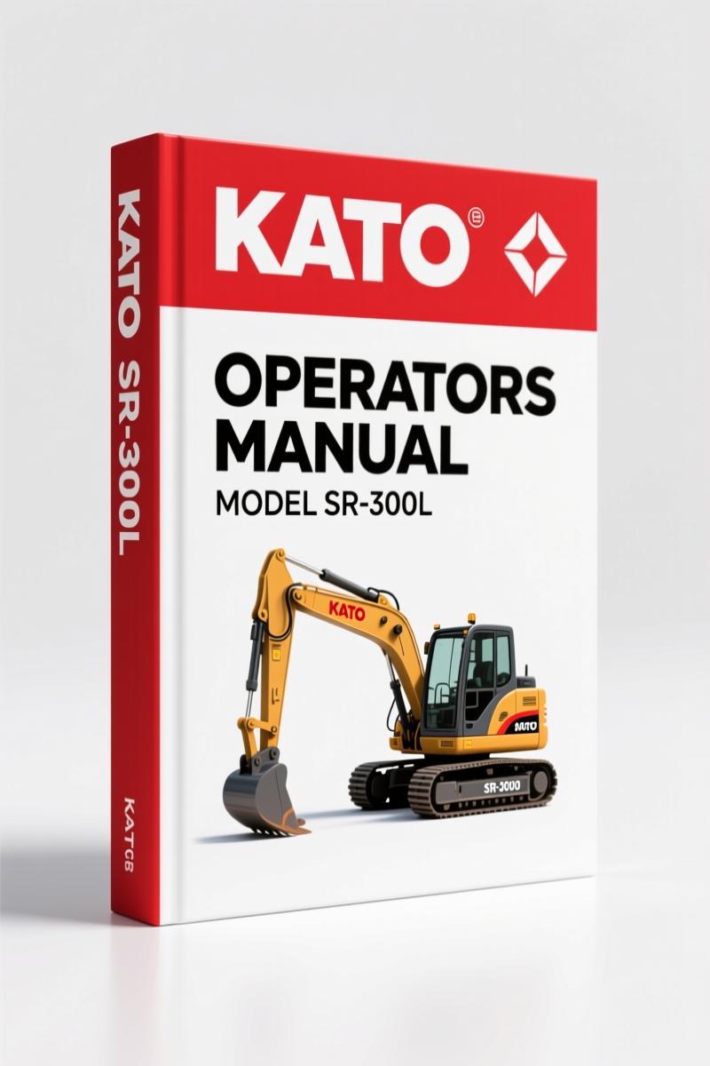
Kato SR-300L, SR-300LS, SR-700L, SR-700LS Service Manual – Factory COR5 Diagnostics
Original price was: $42.60.$30.00Current price is: $30.00.
OEM service manual for Kato SR-300L/300LS/700L/700LS. 85 pages of COR5 control system diagnostics, test modes, and wiring data.
Description
I’ve seen too many guys tear into a Kato rough terrain crane with a third-party schematic and end up chasing ghosts. The COR5 system on these machines – Kato SR-300L, SR-300LS, SR-700L, SR-700LS Service Manual – is not something you guess through. You need the factory book if you want to keep the electronics intact and the hydraulics from dumping oil on the shop floor.
What This 85-Page Service Manual Covers
85 pages isn’t a lot, but every page carries weight. The manual opens with a summary of the COR5 system: layout of devices like the Display I/O (DI), Switch Box, Cluster Meter Panel, Rotary Brush, and Frame Terminals (FT, FT2). Section 1-1 spells out general precautions on handling the COR system – static discharge warnings that aftermarket reprints often skip. Then you hit the real meat: chapter 2 on checks. Connector layout and signal names for every module, rear steering processing with potentiometer characteristics, outrigger horizontal stroke sensor data. That’s the kind of spec you can’t invent on the fly. Chapter 3 tackles troubleshooting with an error display location and a full error code list. Chapter 4 covers replacement of the switch box panel, program changes, and identification plate. Finally, chapter 5 lists program versions and rewriting procedures.
If you’ve ever tried to find the correct DI or FT solenoid output without a wiring diagram, you know the value of the connector pinouts on page 11 and page 23. Page numbers matter when you’re under a crane with a multimeter and ten minutes of daylight left.
KATO Roughter SR-300L Instruction Manual Machine Section covers the mechanical side; this one sticks to the electrical and hydraulic controls.
Understand the COR5 System Before You Start
Section 1-1 warns you about handling the COR control unit: proper grounding, avoiding static discharge, never hot-plugging connectors. Ignore that and you’ll fry the board. The system block diagram in section 1-3 shows how DI, SW BOX, cluster meter, and FT communicate. You need to understand that before you start probing pins. The manual also names every display and control switch – cluster meter panel and switch box layouts – so you know exactly what each button does in test mode.
One mistake I see: guys skip the “functional explanation of each device” because they think they know. Then they connect a frame terminal wrong and short a solenoid output. Read the manual first. It’s 85 pages – you can read it in an hour.
Test Mode Procedures: Pinpointing Electrical Faults
Chapter 2-9 lists test modes A through H. Each one isolates a different part of the system. Test mode A (page 61) checks DI inputs, FT inputs, switch box, and CAN inputs. You don’t need to tear the cab apart; you read the digital display on the switch box and see which sensor is missing. Test mode B (page 64) checks outputs – DI and FT solenoids, CAN outputs. If the outrigger won’t extend, test mode C or D (page 66-68) lets you cycle the solenoids manually. Aftermarket manuals rarely give you this level of diagnostic control.
These test modes save you from swapping parts that aren’t bad. I’ve used them to find a bad frame terminal internal indicator LED in under five minutes. Without the procedure, you’d be chasing a phantom ground for hours.
Troubleshooting with Factory Error Codes
Section 3-2 lists error codes with their display location and meaning. The manual tells you exactly which lamp lights up on the cluster meter panel or switch box when a sensor fails. For example, the misoperation warning buzzer output conditions are spelled out in section 2-6-3. Without those codes, you’re guessing which of the dozen sensor inputs is out of range. The error code list on page 75 covers all the possibilities for the SR-300L and SR-700L series.
Aftermarket reprints often omit these codes or transpose them. OEM factory documentation guarantees the numbers match the actual hardware. Trust only the source.
Who Needs This Manual?
If you own a Kato SR-300L, SR-300LS, SR-700L, or SR-700LS and do your own maintenance, you need this. Also shop owners who don’t want their techs guessing on a $200,000 crane. Beginners can follow the test mode and replacement sections if they read the safety notes first. A real-world use case: replacing the switch box panel (section 4-1). You need the connector layout and the program change procedure (section 4-2) to match the new panel to the machine.
For the vehicle drivetrain, refer to a Manual Transmission resource if needed. The COR system interacts with other subsystems, but this manual stays focused on the electronics and hydraulic controls.
Another external reference: the Manual Transmission manual from the manufacturer can help if you’re tying the crane’s PTO to the truck’s driveline. That’s not covered here.
Related Manuals
- KATO Roughter SR-300L Instruction Manual Machine Section
- KATO SR-700L SR-700LS Service Manual
- KATO MS-200/SR-700L Service Manual
- Does this manual include wiring diagrams?
- It includes connector layouts and signal names but not full wiring diagrams.
- How do I use the test mode functions?
- Turn the key to ON, navigate the switch box to access test modes A through H as described in section 2-9. Each mode tests specific inputs or outputs. For example, test mode A checks DI and FT inputs without disconnecting anything. Follow the step-by-step procedure on page 61-73. The digital display on the switch box shows live data; you can verify sensor signals, solenoid outputs, and CAN bus communication. If you get an error code, cross-reference section 3-2 to identify the fault. The manual also explains how to exit test mode safely. Practice on a non-critical component first to avoid accidentally energizing solenoids.
If you’re serious about keeping these Kato cranes running without cutting corners, access the factory manual.
Additional information
| Brand | Kato |
|---|---|
| Language | English |
3 reviews for Kato SR-300L, SR-300LS, SR-700L, SR-700LS Service Manual – Factory COR5 Diagnostics
You may also like…
-
Sale!
Kato HD1023III Parts Catalog – OEM Parts Identification for Hydraulic Excavator
Original price was: $52.15.$35.00Current price is: $35.00. -
Sale!
Kato KR25H-12, SR-250SP, KR25H-V2 Parts Catalog – 558 Pages | AutoFix Global
Original price was: $70.20.$45.00Current price is: $45.00. -
Sale!
Kato SR-700L, SR-700LS Service Manual – 439 Pages of Factory Specs
Original price was: $41.40.$30.00Current price is: $30.00. -
Sale!
Kato HD2045 Parts Catalog – OEM Parts List for Hydraulic Excavator
Original price was: $41.60.$32.00Current price is: $32.00.
Related products
-
Sale!

1991 Electrical Schematic – 112-Page OEM Wiring Diagram for International 1000-3000 Series
Original price was: $22.75.$17.50Current price is: $17.50. -
Sale!
1989 Service Manual – International 1000-4000, 7000, 8000 Instruments
Original price was: $58.80.$40.00Current price is: $40.00. -
Sale!

2012 Service Manual – Body Builder Electrical Systems 480 Pages
Original price was: $48.28.$34.00Current price is: $34.00. -
Sale!
1992 Electrical Schematic – OEM Wiring Diagrams for International 1000-3800
Original price was: $24.48.$18.00Current price is: $18.00.
Thomas B. –
This is just what I needed. Immediate link after checkout process. Contains precise wiring diagrams for Kato. Saved my weekend project! Thank you.
Richard G. –
I am extremely satisfied with this transaction. It is easily zoomable on my iPad without losing quality. Contains precise schematics for Kato. Saves me a lot of dollars.
diy_master –
This is just what I needed. It is very easy to read on my iPad without losing quality. Contains detailed schematics for Kato. Saved my repair job! Thank you.