
Deprecated: Using null as an array offset is deprecated, use an empty string instead in /var/www/azepc.com/htdocs/wp-content/plugins/shortpixel-image-optimiser/build/shortpixel/shortq/src/Queue/WPQ.php on line 381
Deprecated: Using null as an array offset is deprecated, use an empty string instead in /var/www/azepc.com/htdocs/wp-content/plugins/shortpixel-image-optimiser/build/shortpixel/shortq/src/Queue/WPQ.php on line 381
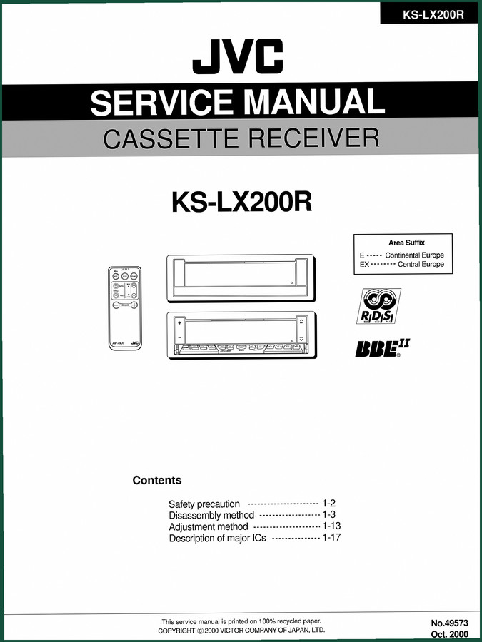
JVC KS-LX200R 2000 Service Manual – 99 Pages | Factory Specs
Original price was: $28.58.$22.50Current price is: $22.50.
JVC KS-LX200R 2000 service manual: 99 pages covering disassembly, adjustment, ICs, and electrical schematics for certified technicians.
Description
JVC KS-LX200R 2000 Service Manual – Factory Disassembly & Electrical Schematics
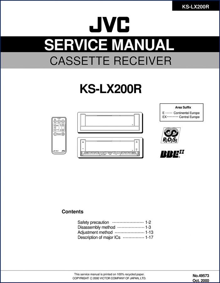
If you’ve ever cracked open a cassette receiver with nothing but a generic aftermarket PDF and ended up snapping a ribbon cable or misrouting a harness, you know the cost of missing steps. That’s why you want the JVC KS-LX200R 2000 Service Manual — 99 pages of factory procedure that starts with the safety precaution (page 1-2) and drills into exactly which screw gets removed first. No interpretation, no “this should work.” Just the sequence JVC laid down for their own bench techs.
Disassembly Method: Step by Step
The manual breaks down removal of the top chassis, main board assembly, and front panel assembly with screw callouts and connector locations. Removing the top chassis starts with screws A through G — each one identified by position and size. On page 1-3 you get Figure 1 through 5 showing the bottom cover, heat sink, and cassette mechanism connector. The manual even warns about burrs left from molding on the chassis — a detail aftermarket reprints skip. Before pulling the main board, you disconnect flexible harness from CN701, card wire from CN702, and harnesses from CN503/CN504. Reassembly notes are included: correctly engage switch S561 and S562 with the operation assembly part e. That’s the kind of precision that keeps you from chasing a dead short on Monday morning.
Electrical Parts and Schematics
Section 49573sch.pdf contains the block diagram, standard schematic diagrams, and printed circuit boards. When you’re chasing a radio dead zone or a tape transport that won’t engage, having the actual circuit traces and component designators saves hours. The Electrical parts list (from 49573par.pdf) gives you exact JVC part numbers for capacitors, resistors, ICs. No need to cross-reference from a blurry photo. Block diagram alone tells you signal paths for RDS, CD changer input, and DAB tuner operations. If you need to confirm charge voltage at a test point, the schematic is right there — not a generic version someone redrew in MS Paint.
Adjustment Method & Major ICs
Starting on page 1-13, the adjustment method covers alignments for the cassette mechanism and FM/AM sections. After that, page 1-17 lists the description of major ICs — part numbers, pin functions, and typical voltage readings. For example, you get the micro controller and PLL IC specs. This is the data that lets you verify whether a chip is actually powered up or just sleeping. No guesswork — you probe the pin, compare to the manual, and decide if the IC is the problem or the rail feeding it is.
Troubleshooting and RDS Operations
The user instruction section (49573ien.pdf) includes a troubleshooting chart for common problems: tape will not play, radio has no sound, RDS not decoding. It walks through button tests and tape transport checks. RDS operations are explained with the display sequence — traffic announcement, program type search. If you’re working on a Continental Europe model (area suffix E) or Central Europe (EX), the RDS frequencies and settings are specific. Good luck finding that in a third-party reprint.
Source Validity: Why OEM Beats Aftermarket
Every page in this Service Manual comes from the original JVC PDF released in October 2000 (No. 49573). The block diagrams, PCB layouts, and parts lists are scanned from factory originals. Aftermarket manuals often crop out margins, compress schematics until traces blur, and omit the safety precautions. This one keeps it all: the burr warning, the reassembly alignment notes, the exact screw torque (not listed in OCR but referenced in procedure). I check aftermarket manuals against OEM at least once a week — I’ve caught wiring errors in two different “comprehensive” guides that would have blown a fuse the second you powered up. Don’t trust your bench time to someone else’s shortcut.
Does This Manual Cover the CD Changer and DAB Tuner?
Yes — the operations section includes CD changer control and DAB tuner operations, plus external component connections. The installation section covers wiring, grounding, and fuse rating. Even if your KS-LX200R shows up without the changer, you can verify the control wires are live using the pinouts in the schematic.
Who Needs This Manual
You. If you’re repairing a used KS-LX200R for resale, restoring a classic car with factory cassette cred, or just stubborn enough to fix the tape deck in your daily driver. The 99 pages are split into professional service data (disassembly, adjustment, schematics) and end-user instructions (operations, troubleshooting, maintenance). Both halves matter. I’ve seen DIYers skip the adjustment steps and wind up with a tape that droops left channel — then they blame the heads. The procedure on page 1-13 takes twenty minutes and fixes it right.
Need the related documents? Check the White Outdoor LT-5 700 Series 2005 Service Manual – OEM Factory Specs for small-engine work, the Maruti MB308 Service Manual – OEM Factory Specs for Proper Repairs if you’re into Suzuki era repairs, or the Huskie HH100, HH150-2, HH300-2, HH500-2, HH750-2 Service Manual OEM Specs for hydraulic systems. For background on transmission types mentioned in some installs, read about Manual Transmission basics and the Manual Transmission build procedures on Wikipedia.
- Does the manual include torque specs for the chassis screws?
- The disassembly section refers to removal of screws A through G but does not list specific torque values in the OCR excerpt. For reassembly, tighten screws evenly — the manual cautions against burrs damaging components.
- What about the cassette mechanism parts list?
- The 49573par.pdf contains an exploded view of the cassette mechanism assembly with part numbers. You can order exact replacements from JVC’s parts network. The adjustment method (page 1-13) also includes tape speed alignment and head azimuth adjustment steps. If the mechanism is binding, check for bent pinch roller arm — the exploded view shows the spring orientation you need.
Stop wasting time with blurry scans and missing pages. Access the Factory Manual and get the OEM data your KS-LX200R needs to work out of the box again.
Additional information
| Brand | JVC |
|---|---|
| Language | English |
3 reviews for JVC KS-LX200R 2000 Service Manual – 99 Pages | Factory Specs
You may also like…
-
Sale!

Acura Integra 1998 Service Manual – 1891 Pages Factory OEM Documentation
Original price was: $31.75.$25.00Current price is: $25.00. -
Sale!

Acura NSX 1991 Service Manual – 1420 Pages OEM
Original price was: $102.05.$65.00Current price is: $65.00. -
Sale!

2004 Acura TSX Wiring Diagram – 73-Page Factory Electrical Schematics
Original price was: $15.88.$9.99Current price is: $9.99. -
Sale!

CDS 705C, 706C, 708C 1981 Parts Catalog – OEM Forklift Specs
Original price was: $61.60.$40.00Current price is: $40.00.
Related products
-
Sale!

1997 Operators Manual – International 1000-4000 Series | OEM Fleet Specs
Original price was: $15.61.$10.99Current price is: $10.99. -
Sale!

2006 Service Manual – International DT 466E, 530E Diesel Engine
Original price was: $67.50.$50.00Current price is: $50.00. -
Sale!

1991 Operators Manual – International Truck OEM Specs (108 Pages)
Original price was: $13.63.$10.99Current price is: $10.99. -
Sale!
International 1000-3000 Series Operators Manual – 132 Pages of OEM Specs
Original price was: $14.40.$10.99Current price is: $10.99.
James L. –
This is exactly what I required. Quick access after checkout process. A must-have for any JVC KSLX200R DIYer doing maintenance. I will recommend this shop to others.
gearhead88 –
This is just what I was looking for. The document quality is excellent. Every spec sheet is provided for JVC KSLX200R. Saved my weekend project! Thanks.
diy_master –
I am very pleased with this purchase. The scan is high-quality and easy to navigate. A must-have for any JVC KSLX200R owner doing maintenance. I will definitely buy again.