
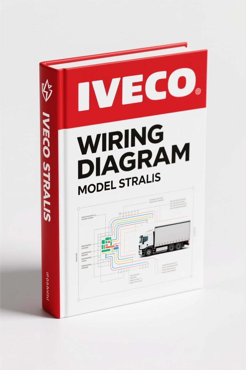
Iveco STRALIS Wiring Diagram – 174 Pages of Factory Circuit Data
Original price was: $38.50.$25.00Current price is: $25.00.
Factory Iveco STRALIS wiring diagram – 174 pages covering BC2, CAN lines, OBD connector, circuit charts, and block diagrams. For certified technicians.
Description
Iveco STRALIS Wiring Diagram – OEM BC2 Diagrams, 174-Page Manual
I’ve seen a lot of electrical gremlins in my time, and a bad wiring diagram is the fastest way to fry a thousand-dollar module. If you’re chasing an intermittent CAN fault or a central lock that won’t unlock on an Iveco STRALIS Wiring Diagram, the last thing you need is a generic schematic that guesses at pin assignments. This 174-page OEM document from Iveco’s own technical publishing arm gives you exactly what the factory uses – no reinterpretation, no third-party redrawing, no lost detail. It’s the same binder the dealer techs get.
Body Computer 2 (BC2): What Changed
Page 3 of this manual lays out the new features due to the introduction of BC2. If you’re working on a STRALIS built after 2007, you’ll see the CAN lines are now routed through the BC2 instead of a separate body computer. That means the central locking, wipers, and some lighting circuits all talk to the BC2 via CAN. The manual gives you the exact CAN line assembly drawing on page 10 – wire colors, connector pinouts, and termination resistors. Without that drawing, you’ll spend hours probing wires that go nowhere.
CAN Lines: Tracing the Network
The CAN line section (pages 4-9) breaks down the network architecture. You get separate diagrams for the high-speed and low-speed CAN, plus the connection points for the F.F.C., R.F.C., D.D.M., P.D.M., and EDC ECM computers. For a professional, this means you can isolate a bus-off condition without disconnecting everything. For the home garage guy, it means you can find that corroded splice behind the headlight housing without replacing the entire chassis harness. The manual also includes the OBD diagnosis connector (blue) pinout on page 12 – critical for getting live data out of the BC2.
OBD Connector Pinout – Page 12
Page 12 gives you the exact pin assignments for the blue OBD diagnosis connector. Most generic OBD pinout charts only cover pins 4,5,6,14,16. Iveco uses pins 1, 9, and 11 for proprietary CAN and K-line signals. If you’re trying to flash the VCM or run a diagnostic scan tool that requires the Iveco-specific protocols, you need this page. Don’t trust a website that lists “standard OBDII” – this manual shows you the real terminal numbers and wire colors pulled from the factory harness.
Central Locking with Remote Control – Page 64
Central locking issues are common on the STRALIS, especially when the remote stops working but the driver door lock still cycles. Page 64 of this manual covers the entire central locking circuit, including the remote-control receiver, the BC2 inputs, and the door actuator wiring. It also includes the circuit charts starting on page 67, where you’ll find voltage drop tables and component locations. One note: the factory uses a white wire with a brown tracer for the unlock signal on the driver door – not the blue/red you’ll see in aftermarket diagrams. This is the kind of detail that saves you from buying a new BC2 that wasn’t bad in the first place.
Why OEM Wiring Diagrams Beat Aftermarket
Aftermarket wiring diagrams are often redrawn from the same source but they remove the connector views, splice locations, and optional equipment branches. This Iveco STRALIS wiring diagram is a scanned reproduction of the official Iveco print 603.93.746 – the same one used by the Iveco commercial network. It includes the BC2, EDC ECM, VCM, EM (PTO), and all the optional modules like the EBM. If you’ve ever tried to trace a DDM power feed from an aftermarket drawing, you know how often they mislabel fuse positions. The original Iveco document doesn’t guess. It tells you exactly which supplementary fuse on page 25 powers the DDM and which remote switch on page 23 controls it.
Who Needs This Diagram?
Home garage owner? If you’re swapping a radio, adding auxiliary lights, or sorting out a door lock that only works with the remote, this diagram will get you the right circuits. Fleet mechanic? You’ll use the CAN line assembly drawing and the VCM pinout to diagnose J1939 bus faults without pulling each module. Tow truck operator? The central locking section gives you the trigger wires for a remote override – handy when the battery is dead and you need to pop the door. This isn’t a guide that holds your hand. It’s the raw factory data you need to fix it right. If you also work on other Iveco vocational models, check out the Iveco Stralis EBS/ESP/EBL Technical Manual for brake systems or the Iveco Stralis Repair Manual for engine overhaul specs. For a complete workshop reference, the IVECO Stralis Workshop Manual covers drivetrain and chassis.
Want to understand the basics of Automotive Wiring before diving in? That’s fine. But once you need the actual pin numbers and splice locations, you’ll want the original. The same applies to Automotive Wiring theory – great for fundamentals, but this manual gives you the Iveco-specific reality.
That’s it. 174 pages of factory wiring diagrams for the Iveco STRALIS with BC2 body computer. No fluff, no reprints, no generic schematics. Just the OEM document from Iveco S.p.A. Customer Service.
- Does this wiring diagram include the Body Computer 2 (BC2) system?
- Yes. Section “NEW FEATURES DUE TO THE INTRODUCTION OF BODY COMPUTER 2 (BC2)” starts on page 3, and the BC2 unit pinout is on page 31.
- What page shows the OBD connector pinout?
- Page 12. It covers the blue OBD diagnosis connector with all 16 pins, including the Iveco-specific pins 1, 9, and 11. The receptacle connector pinout is on page 15.
- Can I use this manual to troubleshoot central locking that only works from the driver door?
- Yes. Page 64 covers the central locking with remote control circuit. The manual lists each actuator wire color and the BC2 input. It also includes the circuit charts from page 67 for voltage drop testing. Note that the unlock signal wire from the driver door is white/brown – aftermarket diagrams often show blue/red, which will cause you to misdiagnose a bad switch as a failed BC2.
- Is this a genuine Iveco publication or a third-party reprint?
- It’s a scan of the official Iveco printing 603.93.746, 1st edition March 2007, produced by Iveco Technical Publications in Turin, Italy. No aftermarket redraws. The OBD pinout, CAN drawing, and central locking data are from the original Iveco sources.
Stop chasing electrical ghosts with a photocopy of a photocopy. Access the Factory Manual from AutoRepairManuals and get the real Iveco STRALIS wiring diagram with BC2 coverage, CAN line assembly, and 174 pages of factory-correct data.
Additional information
| Brand | Iveco |
|---|---|
| Language | English |
2 reviews for Iveco STRALIS Wiring Diagram – 174 Pages of Factory Circuit Data
You may also like…
-
Sale!
Iveco Cursor 13, Cursor 78, GE/GS 250E, GE 400E 2006 Tech Manual
Original price was: $92.40.$60.00Current price is: $60.00. -
Sale!
Iveco AD 380 T 42 WH 2005 Technical Manual – Factory Specs
Original price was: $79.00.$50.00Current price is: $50.00. -
Sale!
Iveco EuroCargo Tector Repair Manual – Electrical/Electronic System 192 Pages
Original price was: $76.20.$60.00Current price is: $60.00. -
Sale!
Iveco STRALIS Repair Manual – Factory Engine Specs & Procedures
Original price was: $85.15.$65.00Current price is: $65.00.
Related products
-
Sale!

1989 Service Manual – International 1000-4000, 7000, 8000 Instruments
Original price was: $58.80.$40.00Current price is: $40.00. -
Sale!

Service Manual – International HS 2.8L Engine – 130 Pages of Factory Specs
Original price was: $56.40.$40.00Current price is: $40.00. -
Sale!

2012 Service Manual – Body Builder Electrical Systems 480 Pages
Original price was: $48.28.$34.00Current price is: $34.00. -
Sale!
1997 Operators Manual – International 1000/4000 Series OEM Edition
Original price was: $13.49.$9.99Current price is: $9.99.
Robert M. –
This is exactly what I needed. Instant access after payment. Contains detailed bolt torque specs for Iveco. Saves me a lot of time.
diy_master –
This is exactly what I needed. The pages are clean and easy to navigate. Contains clear bolt torque specs for Iveco. Saves me so much time.