
Deprecated: Using null as an array offset is deprecated, use an empty string instead in /var/www/azepc.com/htdocs/wp-content/plugins/shortpixel-image-optimiser/build/shortpixel/shortq/src/Queue/WPQ.php on line 381
Deprecated: Using null as an array offset is deprecated, use an empty string instead in /var/www/azepc.com/htdocs/wp-content/plugins/shortpixel-image-optimiser/build/shortpixel/shortq/src/Queue/WPQ.php on line 381
International Truck And Engine 5000, 9200, 9400, 9900 Electrical Schematic – 51 Pages
Original price was: $14.18.$10.99Current price is: $10.99.
Factory electrical circuit diagrams for International 5000, 9200, 9400, 9900 trucks. 51 pages, OEM release AE08-52509.
Description
International Truck And Engine 5000, 9200, 9400, 9900 Electrical Schematic – Factory Wiring Diagrams
You have a 2002 International 9400 with a trailer ABS light that stays on, or a 9200 that won’t crank. You grab a generic wiring diagram from some online forum – and the wire colors don’t match, the relay location is wrong. That is time you don’t get back. This manual is the real thing: International Truck And Engine 5000, 9200, 9400, 9900 Electrical Schematic – 51 pages of OEM circuit diagrams straight from Navistar. These are the exact prints the technicians used on the assembly line. No aftermarket redraw. No guesswork on which pin does what. Every diagram references the actual power distribution center layout, fuse numbers, and ground locations.
Chapter 9: Chassis Accessories – Air Dryer and ABS/ATC
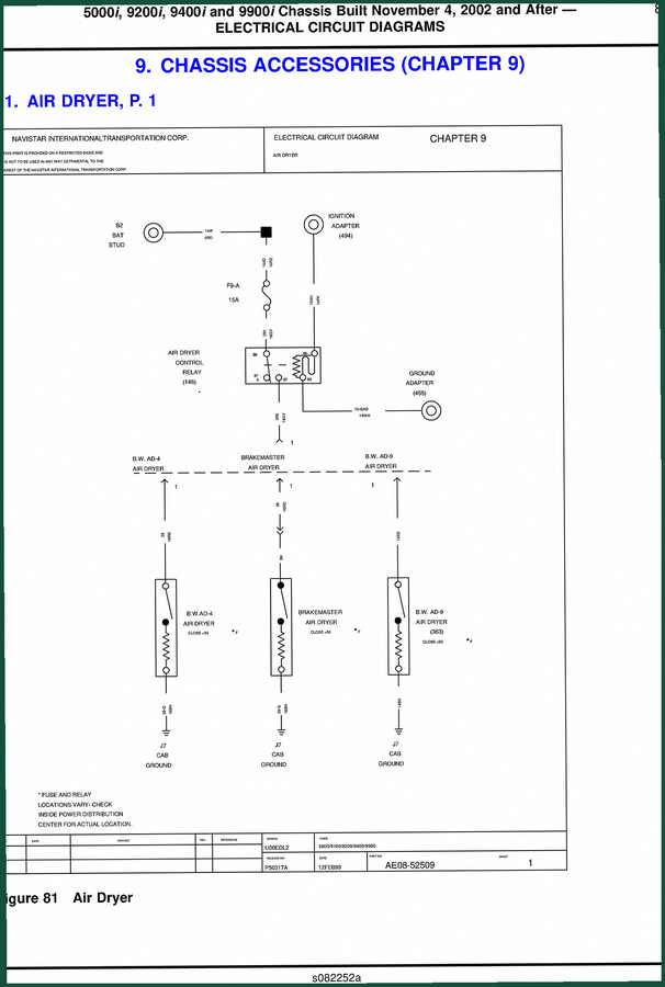
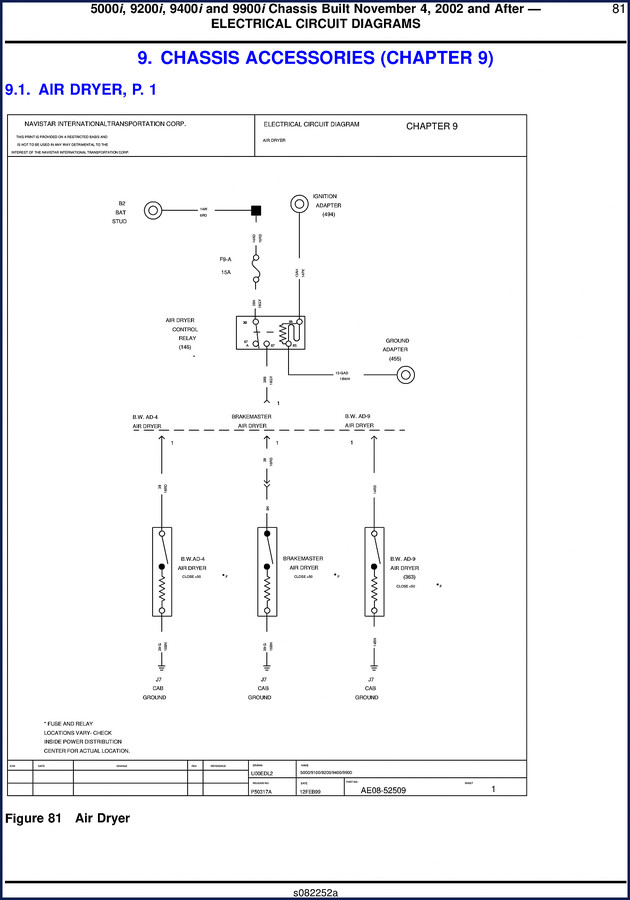
The manual starts with Chapter 9, covering chassis accessories. On page 1 you get the air dryer circuit – B.W. AD-4, AD-9, Brakemaster units. It shows the 15A fuse (F9-A), the control relay (146), and the ignition adapter (494). Wire gauge is clearly marked: 14W 6RD for the battery feed, 14AD 16RD to the relay. That level of detail matters when you are diagnosing an air dryer that won’t cycle. Then on page 2, the ABS/ATC (Bendix) diagram gives you the full Bendix ABS wiring including the ABS warning lamp relay (165), the traction control switch (511), and the trailer ABS lamp circuit. The manual even notes the revision history – connector changes, added trailer lamp. That is factory revision tracking you won’t find in a third-party copy.
Does This Manual Cover Your Specific Year and Model?
This schematic applies to the 5000i, 9200i, 9400i, and 9900i chassis built November 4, 2002 and after. If you have an earlier build, the wiring changed. The cover page lists “5000/9100/9200/9400/9900” as a part number reference, but the actual diagrams are for the “i” series. For the 9100 series, check the related CF500/CF600 Electrical Circuit Diagrams Service Manual – different platform. You need the right date range or you’ll be chasing ghosts.
3 Reasons to Trust This OEM Schematic Over Aftermarket
First, every diagram shows the exact wire colors and gauge (e.g., 14PK, 16GY). Aftermarket manuals often simplify to “red” or “black” – useless for tracing a harness. Second, fuse and relay locations are printed right on the diagram with a warning: “FUSE AND RELAY LOCATIONS VARY – CHECK INSIDE POWER DISTRIBUTION CENTER FOR ACTUAL LOCATION.” Third, the schematic uses the same connector numbers and ground points as the truck. One example: ground adapter (455M) and ABS feed (5710) – those numbers match the service parts catalog. That means you can order the correct pigtail if a connector is damaged.
Understand the Wire Color Codes Before You Start
Each wire in the diagram is labeled with a color code and a circuit number. For instance, 94K 10GY is a 10-gauge gray wire for the ABS ignition feed. If you are adding a relay or splicing into the circuit, you must match both the gauge and the circuit number to avoid overloading. The manual also shows splice locations – e.g., “94-GA was at Conn 165” – a revision that tells you where to find it on later builds. Do not use a generic wiring chart; stick to the factory codes from this document. For an extra layer of verification, refer to SAE International Standards for wire color conventions, though this manual follows Navistar’s own system.
Fuse and Relay Locations: The Manual’s Warning
The schematic repeatedly states: “FUSE AND RELAY LOCATIONS VARY – CHECK INSIDE POWER DISTRIBUTION CENTER FOR ACTUAL LOCATION.” This is not a loophole; it’s a safety reminder. On page 1, fuse F9-A is a 15A for the air dryer; on page 2, fuse F10-A is a 30A for the ABS ignition relay. If you assume the location from another truck, you can blow fuses or cause a short. Use the power distribution center label in your truck to confirm the slot. For the ABS/ATC section, the diagram even lists relay numbers (152M, 165) so you can cross-reference with the PDC layout. That’s precision you don’t get from a scraped PDF.
Electrical Safety: What the Manual Doesn’t Tell You
This manual doesn’t hand-hold you on safety – it’s a wiring diagram, not a training course. You need to disconnect the batteries before probing, use a digital multimeter with fused leads, and never pierce insulation with a test light. The high-current circuits (battery stud B2, 6RD wire) can arc weld a screwdriver. If you are not comfortable reading schematics, get a shop to do the diagnosis. But if you understand how to read a ladder diagram, this 51-page document gives you everything to troubleshoot the electrical system on these International trucks. For quality standards on automotive electrical components, see ISO Quality Standards.
That matters when you are 400 miles from the nearest dealer.
Related manuals you may need:
- CF500/CF600 Electrical Circuit Diagrams Service Manual – for smaller International chassis.
- International Truck CF 500 CF 600 Wiring Diagram – earlier models.
- International Truck 5000i 9200i 9400i 9900i 2002 Wiring Diagram – same platform but different focus.
- Is this manual for the 2002 model year?
- Yes, it covers chassis built November 4, 2002 and after.
- Can I use this schematic for the 9100 series?
- No, this manual specifically covers 5000i, 9200i, 9400i, 9900i. The 9100 series is referenced on the drawing border as part number AE08-52509, but the actual circuits are for the “i” series. If you have a 9100, check the CF500/CF600 manual – the 9100 is a different electrical architecture. Using this schematic on a 9100 will give you wrong wire colors and connector assignments. That will cause misdiagnosis and potential electrical damage. Stick to the correct model list.
Stop wasting time with diagrams that don’t match the wires in your hand. Access the Factory Manual and get the exact circuits for your International 5000, 9200, 9400, or 9900.
Additional information
| Brand | International Truck And Engine |
|---|---|
| Language | English |
4 reviews for International Truck And Engine 5000, 9200, 9400, 9900 Electrical Schematic – 51 Pages
You may also like…
-
Sale!
International CF 500, CF 600 Wiring Diagram – 197 Pages
Original price was: $41.40.$30.00Current price is: $30.00. -
Sale!
International Truck And Engine CF 500, CF 600 2005 Service Manual – 77 Pages
Original price was: $38.70.$30.00Current price is: $30.00. -
Sale!
International Truck And Engine 5000i, 9200i, 9400i, 9900i 2002 Wiring Diagram
Original price was: $35.50.$25.00Current price is: $25.00. -
Sale!
International Truck And Engine CF 500, CF 600 2008 Electrical Schematic – Factory Wiring
Original price was: $14.49.$9.99Current price is: $9.99.
Related products
-
Sale!

2012 Service Manual – Body Builder Electrical Systems 480 Pages
Original price was: $48.28.$34.00Current price is: $34.00. -
Sale!

1991 Electrical Schematic – 112-Page OEM Wiring Diagram for International 1000-3000 Series
Original price was: $22.75.$17.50Current price is: $17.50. -
Sale!
1992 Electrical Schematic – International 1000/3000/4000/2554 OEM Wiring Diagrams (132 Pages)
Original price was: $26.40.$20.00Current price is: $20.00. -
Sale!

2011 Parts Catalog – International 7400 SFA 6X6 – 1886 Pages of OEM Part Numbers
Original price was: $32.00.$25.00Current price is: $25.00.
gearhead88 –
Superb resource! The scan is high-quality and easy to navigate. Every wiring layout is provided for International Truck And Engine Truck. Saved my weekend project! Thanks.
Thomas B. –
Excellent quality! The document quality is excellent. Contains precise wiring diagrams for International Truck And Engine. Saved my repair job! Thanks.
James L. –
This is just what I required. The PDF is very clear. Contains detailed wiring diagrams for International Truck And Engine. I will recommend this shop to others.
William H. –
Highly recommended! Quick access after checkout process. A must-have for any International Truck And Engine Truck owner doing repairs. I will recommend this shop to others.