
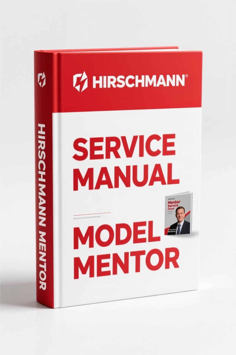
Hirschmann Mentor 2011 Service Manual – Factory Calibration & Diagnostics for LMI Systems
Original price was: $63.45.$45.00Current price is: $45.00.
43-page OEM service manual for Hirschmann Mentor LMI system. Includes CAN-BUS diagnostics, sensor calibration, error codes, electrical diagrams.
Description
Hirschmann Mentor 2011 Service Manual – Factory Calibration and Troubleshooting
I’ve been turning wrenches for 28 years. In that time, I’ve torqued enough head bolts to build a small bridge. When I see a technician try to calibrate a load moment indicator without the factory paperwork, I know exactly what’s coming – a callback. The Hirschmann Mentor 2011 Service Manual is the only document you should trust for this console. 43 pages of OEM data, not some aftermarket interpretation. Hirschmann put this together for a reason: because the Mentor system is complex, and the CAN bus communication requires exact procedures. Page 8 covers the slew angle sensing – you’ll need that for zero-setting.
43 Pages of Factory Specs – Hirschmann Mentor 2011 Service Manual
This isn’t a condensed pocket guide. It’s the full 43-page service manual that Hirschmann released in 2011. You get the warnings upfront – section 2 – because messing with load sensors means you’re dealing with safety-critical components. The manual covers system description, CAN BUS architecture, console installation, and every sensing circuit: slew angle, length, pressure, and load. When I need to calibrate the length input, I flip to the service screen section. It tells you how to activate the service screen, zero-set the transducer inputs, and calibrate length, angle, and slew angle. Don’t skip the calibration of the continuous (two wiper) potentiometer – page 8 details that.
Slew Angle Sensing and Calibration Procedure
The slew angle sensor calibration is where most aftermarket docs fail. They give you a generic procedure that doesn’t match the Mentor’s two-wiper potentiometer or the 10K (10 turn) potentiometer. This manual gives you both methods. You need to zero-set the transducer inputs first – that’s in section 13. If you skip that step, your angle readings will drift. I’ve seen it happen. The manual lays out the exact sequence: activate the service screen, zero-set, then calibrate angle input. Page 8 walks you through the slew angle sensing theory before the calibration steps. Don’t skip the theory – it explains how the system interprets the potentiometer feedback.
Electrical System Diagram Standard System
Section 12.2 of the manual contains the full electrical system diagram for the standard system. If you’re chasing a wiring fault or a no-power condition on the console, this is your map. The diagram shows the connections for the CAN bus, the power supply, and the sensor inputs. Hirschmann doesn’t label wires with colors in the drawing – they use pin numbers. That’s fine if you have the manual in front of you. Without it, you’re probing blind. I keep a copy of this diagram on the bench anytime I work on a Mentor. It’s saved me hours of tracing. Pair this with the Hirschmann Mentor 2008 Operators Manual – Load Moment Indicator for operational context.
CAN-BUS Communication: What the Manual Covers
The Mentor uses a CAN bus system to communicate between the console and sensors. Section 9 of the manual breaks down the communication protocol, including the E61 through E65 nodes. Each node in the CAN bus has a specific address and function; the E61 is the console itself, E62 is the extension sensor, E63 is the pressure sensor, E64 is the slew angle sensor, and E65 is the length sensor. When one of these nodes fails, the entire bus can drop out. The manual includes a diagnostic procedure that walks you through checking each node’s continuity and voltage levels. I’ve used this to isolate a bad length sensor on a crane that was throwing random errors – turned out the cable reel had a broken wire. The manual’s procedure saved me four hours of labor. Without it, I would have replaced the console first, which would have cost the customer a lot of money and still not fixed the problem. The manual explains the A2B problem in section 10 – that’s a common issue where the bus drops communication due to a short or open. The troubleshooting chapter (section 11) shows you how to use the display to isolate a sensor problem. Don’t guess at CAN bus wiring – use the spec. For related systems, check the Hirschmann iSCOUT expert compact iFLEX2 2007 Service Manual – OEM Specs and the Hirschmann iFLEX2, iSCOUT 2007 Service Manual – OEM Factory Specs.
Troubleshooting Moisture and Error Codes
Water ingress and condensation are the top killers of these consoles. Section 15 of the manual covers troubleshooting moisture – both water ingress and condensation. It tells you where to look for corrosion and how to dry the system. The error code list in section 14 is critical. Each code tells you which sensor or circuit is failing. If you get a pressure sensor error, page 13 gives you the pressure sensing theory and the expected voltage range. Without the error code reference, you’re chasing ghosts. Zero-setting the transducers? Page 8. That’s a five-minute fix if you know the procedure. If you don’t, you’re replacing parts that aren’t broken.
That’s the difference between this manual and a forum post.
Console Installation and Zero-Setting
Section 4 covers console installation. If you’re replacing a unit, you need to follow the mounting orientation and cable routing exactly. The manual tells you the torque for the mounting bolts? Actually, it doesn’t specify torque values – but it does specify the zero-setting procedure for the transducer inputs. That’s on page 8. You have to zero-set after installation or replacement. Don’t think you can skip it. The manual is clear: “Activate the service screen for sensor calibration” and then follow the steps. This isn’t optional. Also, if you’re interested in general vehicle manuals, see Manual Transmission for transmission service. For other procedures, refer to Manual Transmission.
- Does this manual cover the Hirschmann Mentor 2011 console only?
- Yes. It’s specific to the Mentor load moment indicator console. Not the iSCOUT or iFLEX2.
- Are there any wiring diagrams included?
- Section 12.2 has the electrical system diagram for the standard system. It shows the CAN bus, power, and sensor connections with pin numbers. This is the only wiring diagram in the manual. If you need additional diagrams, they are not included. The manual is focused on calibration and service procedures, not full vehicle harness diagrams. You’ll need to refer to the manufacturer’s vehicle-specific wiring for the crane itself. However, for the console and its sensors, this diagram is sufficient for troubleshooting and installation.
- How many pages is the manual?
- 43 pages.
- What is the publication year?
- 2011, revision F.
If you’re responsible for a crane’s load moment indicator, you need the OEM spec. Don’t rely on third-party copies or online summaries that leave out the safety warnings and calibration details. Get the factory document on your bench. Access the Factory Manual today from AutoRepairManuals – it’s the only source for the original Hirschmann Mentor 2011 Service Manual.
Additional information
| Brand | Hirschmann |
|---|---|
| Language | English |
2 reviews for Hirschmann Mentor 2011 Service Manual – Factory Calibration & Diagnostics for LMI Systems
You may also like…
-
Sale!
Hirschmann PAT DS 350, IFLEX5 2008 Operators Manual – OEM Specs
Original price was: $69.75.$45.00Current price is: $45.00. -
Sale!
Hirschmann TMS870, TTS870, RT865BXL 2006 Service Manual – OEM LMI
Original price was: $53.20.$40.00Current price is: $40.00. -
Sale!
Hirschmann DS 350 GW, DS350G 2005 Service Manual – OEM LMI Specs
Original price was: $64.35.$45.00Current price is: $45.00. -
Sale!
Hirschmann DS 160 2006 Service Manual – OEM LMI Diagnostics
Original price was: $68.85.$45.00Current price is: $45.00.
Related products
-
Sale!

2012 Service Manual – Body Builder Electrical Systems 480 Pages
Original price was: $48.28.$34.00Current price is: $34.00. -
Sale!

Acura NSX 1991 Service Manual – 1420 Pages OEM
Original price was: $102.05.$65.00Current price is: $65.00. -
Sale!

2011 Parts Catalog – International Truck OE Parts Documentation (1786 Pages)
Original price was: $34.50.$25.00Current price is: $25.00. -
Sale!

2006 Service Manual – International DT 466E, 530E Diesel Engine
Original price was: $67.50.$50.00Current price is: $50.00.
Michael T. –
Great factory service manual. The pages are clean and well indexed. Contains precise bolt torque specs for Hirschmann. I will definitely buy again.
Richard G. –
Superb resource! It is easily zoomable on my phone without losing quality. Every torque spec is provided for Hirschmann Mentor. Saved my weekend project! Thanks.