
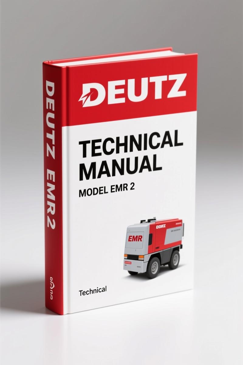
Deutz EMR 2 Technical Manual – OEM Electronic Governor Specifications
Original price was: $38.40.$30.00Current price is: $30.00.
Factory Deutz EMR 2 Technical Manual with complete system description, diagnostic blink codes, and connection diagrams. 118 pages of OEM specifications.
Description
Deutz EMR 2 Technical Manual – What the Factory Expects You to Know
If you are tearing into a Deutz engine with the EMR 2 electronic governor and you have been relying on aftermarket wiring diagrams or generic diesel injection info, you are asking for a burned control unit. The EMR 2 Technical Manual is what Deutz itself uses. 118 pages of German engineering translated into English on the facing pages. That is not a reprint—it is a direct scan of the original 03/02 publication. You get the same pin assignments, the same diagnostic flows, the same fuel-limitation curves that Deutz factory techs follow.
Over the years I have seen too many shops fry an EMR 2 because they guessed the plug pinout or skipped the step about pulling the connector before welding. That stuff is in Chapter 2 – Important Notes. Section 2.4 through 2.6 covers customer-side wiring, plug connections, how to remove a plug without bending terminals, and the exact procedure for electrical welding near the controller. Miss that and you might as well set your diagnostic budget on fire.
What the EMR 2 Technical Manual Covers
Chapter 3 – System Description walks through the EMR 2 utilization, system overview, and basic equipment. Chapter 4 – System Functions is where the meat lives: speed control, set point settings, fuel quantity limitation (the “performance curve” or Dachkurve), droop control, engine start/stop, LDA function, temperature-dependent start control, speed throttling via input F7, engine protection functions, altitude correction, fuel volume control, emergency running (limp home), and cold start installation. Every one of those subsections tells you what the controller expects to see and what happens if it doesn’t.
If you are chasing a no-start or a derate condition, Section 4.15 on limp home mode is where you start. The manual tells you exactly which inputs trigger limp home and what fuel map the controller falls back to. Aftermarket compilations never get that right because they don’t have the OEM calibration data.
Installation Guidelines: Wiring and Welding Precautions
Chapter 2 is short but I am going to call it out because people skip it. Section 2.4 – Customer side wiring, plug connection tells you the wire gauge, the terminal crimp specs, and how to verify the connector is fully seated. Section 2.6 – Electrical welding gives a step-by-step: disconnect battery, disconnect EMR 2 connector, clamp ground as close to the weld area as possible. I have seen three ECMs killed by welders who ignored that. This manual is your insurance against that kind of damage.
For the full wiring reference, flip to Chapter 12 – Connection diagrams. Three sheets: vehicle/unit side, engine side sheet 1, engine side sheet 2, plus a CAN-bus and diagnostic line diagram. No vague line art—factory Deutsch connector drawings with pin numbers and wire colors.
Speed Control and Limp Home Mode: What the Manual Teaches
Speed control (Section 4.3) covers droop and isochronous operation, set point sources, and ramp rates. If you are using the EMR 2 in a generator set or a pump application, the set point configuration in Section 4.4 tells you how to wire potentiometers or 4-20 mA signals without guessing. Fuel quantity limitation (Section 4.5) includes a performance curve that the aftermarket cannot replicate because it comes from Deutz engine dyno data.
Limp home (Section 4.15) is not a one-line description—three paragraphs plus a table of fault conditions. The manual also explains the cold start assist (Section 4.16) and altitude correction (Section 4.13), both of which affect fueling in ways that are easy to misdiagnose. With this PDF you confirm the logic, not the parts store clerk’s opinion.
Diagnostic Button and Self-Diagnostic Mode
You do not always have SERDIA software on site. Chapter 7 – Diagnostic Button and Fault Indicator Lamp covers three methods: self-diagnostic without pressing the button, diagnostic with button and blinking error codes, and full diagnostic with SERDIA software. The blink codes are in the manual—no hunting on forums. Section 7.2 lists every error code and what it means. That alone saves an hour of head-scratching.
The manual also explains how to replace control unit and actuator (Chapter 8), including the tricky pairing of EMR with EMR2 and the combination of old and new parts. If you are swapping an actuator without the factory procedure, you risk the calibration mismatch that causes hunting or overspeed. This manual gives you the sequence.
Technical Data: Pin Assignments and Sensor Specs
Chapter 9 – Technical Data is three pages of signal specifications, plug assignments, and sensor data. If you need to confirm that your speed sensor is within resistance range or that your actuator coil draws the right current, this is the page. Plug assignments are given for the 48-pin and 24-pin connectors with signal names, direction, and electrical characteristics. No third-party reinterpretation—Deutz original.
Aftermarket manuals often condense this into one generic table. This factory manual gives you the full signal specification, including frequency ranges for the speed input and PWM outputs for the actuator.
Related Manuals for Deutz Engines
If your engine uses an earlier governor or a different controller, check these factory documents:
- Deutz 413 F, 413 FW, 413 F/FW/FC 1988 Technical Manual – Factory OEM – for air-cooled diesel engines with mechanical fuel injection.
- Deutz MVS 1998 Technical Manual – OEM Specs, Wiring, Diagnostics – for Deutz medium-vertical engines with electronic control.
- Deutz EMR 3 Technical Manual – CAN Bus Spec for Engine Diagnostics – the next-generation EMR with full CAN bus integration.
For general background on governor systems and diesel control, refer to Manual Transmission theory articles on proper engine braking and drivetrain matching. A solid understanding of how a Manual Transmission couples to an engine helps when setting droop curves.
- Does this manual cover the Deutz EMR 2 for all engine models?
- Yes. The manual covers the EMR 2 governor itself, not specific engine models. The pin assignments, diagnostics, and configuration apply to any Deutz engine equipped with the EMR 2 controller.
- Can I use this manual to diagnose error codes without the SERDIA software?
- Yes, Chapter 7 covers the built-in diagnostic button and blink codes. You can read two-digit fault codes without any software, just the lamp and the button. The manual lists every code with causes and corrective actions.
- What safety precautions are listed for electrical work?
- Section 2.4 through 2.6 covers customer-side wiring, proper plug removal to avoid bent pins, and critical instructions for electrical welding near the EMR 2. The welding section specifies: disconnect the battery, unplug the EMR 2 connector, attach the welding ground clamp as close to the weld area as possible, and never allow welding current to pass through the controller. Ignoring these steps can destroy the control unit instantly. The manual also warns against modifying wiring without referring to the pin assignment tables in Chapter 9. That kind of detail is missing from aftermarket summaries.
- Are the plug assignments and sensor data included?
- Yes. Chapter 9 gives complete plug assignments for the 48-pin and 24-pin connectors, signal specifications, and sensor data including resistance and output voltage ranges.
When you work on a Deutz EMR 2, having the factory documentation means you stop guessing and start diagnosing. Access the Factory Manual directly from AutoRepairManuals before you touch another wiring harness.
Additional information
| Brand | Deutz |
|---|---|
| Language | English |
2 reviews for Deutz EMR 2 Technical Manual – OEM Electronic Governor Specifications
You may also like…
-
Sale!
Deutz 1012, 1013 2007 Workshop Manual – Factory Engine Service Specs
Original price was: $86.40.$60.00Current price is: $60.00. -
Sale!
Deutz 912, 913 2002 Workshop Manual – Factory Specs
Original price was: $72.00.$60.00Current price is: $60.00. -
Sale!

Deutz 912, 913 Workshop Manual – Factory Specs for Technicians
Original price was: $89.05.$65.00Current price is: $65.00. -
Sale!
Deutz BFM 1015 2002 Workshop Manual – OEM Service Data
Original price was: $91.20.$60.00Current price is: $60.00.
Related products
-
Sale!

2011 Parts Catalog – International Truck OE Parts Documentation (1786 Pages)
Original price was: $34.50.$25.00Current price is: $25.00. -
Sale!

2011 Parts Catalog – International 7400 SFA 6X6 – 1886 Pages of OEM Part Numbers
Original price was: $32.00.$25.00Current price is: $25.00. -
Sale!

2005 Parts Catalog – International NGD 3.0 L Engine (77 pages)
Original price was: $44.70.$30.00Current price is: $30.00. -
Sale!

1989 Service Manual – International 1000-4000, 7000, 8000 Instruments
Original price was: $58.80.$40.00Current price is: $40.00.
gearhead88 –
Perfect factory service manual. It is easily zoomable on my laptop without blur. It guided me to rebuild my Deutz EMR engine. Saves me hundreds of dollars.
Robert M. –
I am very pleased with this manual. Instant access after payment. Every wiring layout is provided for Deutz EMR. Saves me hundreds of dollars.