
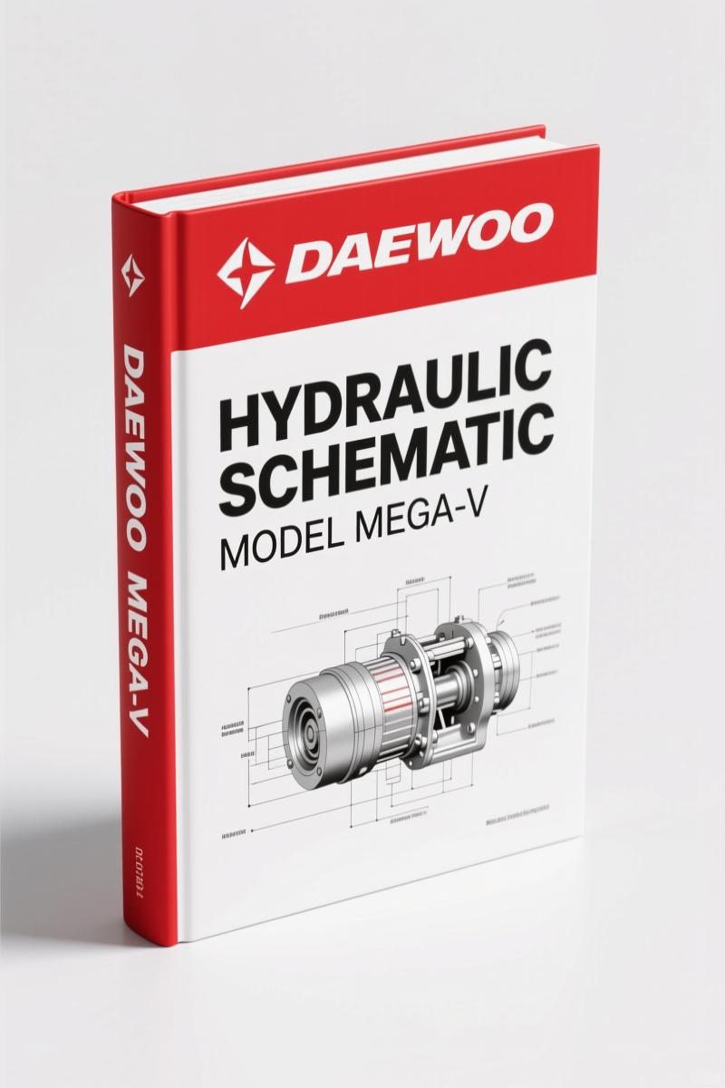
Daewoo MEGA-V 2002 Hydraulic Schematic – OEM Factory Documentation
Original price was: $36.50.$25.00Current price is: $25.00.
Official 2002 Daewoo MEGA-V hydraulic schematic, 64 pages covering pumps, brake/pilot supply, steering, and loader control valves for professional shops.
Description
Daewoo MEGA-V 2002 Hydraulic Schematic – What You Get
Let’s cut through the marketing. You’ve got a Daewoo MEGA-V wheel loader that’s losing brake pressure or the pilot circuit is acting up. The aftermarket diagrams you’ve been chasing? They’re guesses dressed up as prints. This 64-page Daewoo MEGA-V 2002 Hydraulic Schematic is the exact document Daewoo Heavy Industries issued to their own techs in November 2002. No reprints, no third-party redraws, no missing lines. If you’ve ever torqued a fitting to a spec from a Chilton’s and watched it leak, you know the difference.
Page 1 starts with the system overview – reservoir, pump, oil cooler, priority valve, brake/pilot supply, steering unit, valve block, joystick valve, and control valve. That single page shows you how all four circuits (loading, steering, brake, pilot control) share one common reservoir. Understanding that flow path before you start wrenching keeps you from ordering parts you don’t need. I’ve seen guys replace a pump when the issue was a clogged priority valve – this schematic stops that waste.
Brake/Pilot Supply System: Two Variations Covered
The manual splits the brake/pilot supply into two sections: Chapter 5 for the standard system (pages 15–29) and Chapter 6 specifically for M300-V, M400-V, and M500-V models (pages 30–32). That’s not a typo – the larger loaders use a different supply valve arrangement. If you’re working on an M160-V or M200-V, you follow Chapter 5. Grab the wrong diagram and you’ll be chasing a ghost. Page 15 shows the accumulator charging circuit, the pilot pressure reducing valve, and the connections to the fan motor (optional). Brake system diagnostics start here.
What Torque Values Are Listed?
This is a hydraulic schematic, not a service manual. You won’t find fastener torque tables here. What you do get are exact OEM port designations, line sizes, and pressure test points. For torque specs on the actual hydraulic fittings, you need the corresponding factory service manual for your MEGA-V model. However, if you need to identify which port on the priority valve goes to the steering unit or where the unloader valve taps into the pilot supply, this schematic is the only reliable source. The factory print uses Daewoo’s own part numbering – cross-referencing with the parts catalog Daewoo BUS DV11, DL08, DL06 2008 Parts Catalog – OEM Factory gets you the correct O-rings and seals.
3 Critical Sections for Diagnosing Pressure Problems
When a loader drops its bucket fast or the steering gets heavy, most techs jump straight to the pump. The schematic shows you three places to check first:
• Priority valve (Chapter 7) – ensures steering gets oil before the loader circuit. If the priority spool sticks, the steering slows down. Chapter 7 covers the M160-V through M300-V. For M400-V and M500-V, the flow amplifier in Chapter 11 changes the priority logic.
• Brake/pilot supply valve (Chapters 5 & 6) – a failed pilot relief will kill your joystick response. The schematic traces the pilot oil path from the pump through the supply valve to the joystick valve block.
• Unloader valve (Chapter 12) – this valve dumps pump flow when the accumulators are full. If it sticks open, your brakes won’t build pressure. If it sticks closed, you overpressurize the pilot circuit. Page 48 shows the internal pilot lines and the test port locations.
Fluid Viscosity: Page 1 Specs You Can Trust
The general section on page 1 of the manual calls out specific ISO viscosity grades based on ambient temperature. From -10°F to 32°F, use ISO 32 anti-wear hydraulic fluid. From 32°F to 85°F, switch to ISO 46. Above 85°F up to 113°F, go with ISO 68. The manual explicitly says not to use motor oil due to additive differences. That’s the kind of detail you only get from a factory document – aftermarket manuals gloss over fluid specs. If your MEGA-V is running in San Antonio heat, you want the ISO 68 in the system. This manual tells you why.
Source Authenticity: What “OEM” Actually Means Here
This file was scanned from the original Daewoo Heavy Industries & Machinery Ltd. training document, part number 6028-7090, dated November 02, 2002. It’s a true factory hydraulic schematic – not a reprint from a third-party publisher who traced the lines and left out a check valve. Every page is a direct copy of the original. The flow diagrams use Daewoo’s own component symbols, and the system theory text (pages 1–2) explains how the brake circuit integrates with the pilot control circuit. If you’ve ever tried to use a generic hydraulic schematic from a Chilton’s or Haynes on a Korean wheel loader, you know the frustration – wrong port labels, missing option variations. This manual eliminates that.
For related factory documentation, check the Daewoo BUS DV11 DL08 GE12TI GE08TI 2004 Parts Catalog for engine-specific hydraulic pump mounts, or the Daewoo BUS BH120F 2009 Parts Catalog – OEM Factory Specs for bus applications that use similar steering circuits.
One more thing about this hydraulic system: it uses a dedicated anti-wear hydraulic fluid, and the cooler circuit is tied to the engine radiator assembly. Heat buildup degrades seal life fast. The schematic identifies the oil cooler bypass and the optional fan motor supply valve. If you’re retrofitting a cooler, this diagram shows you exactly where the return line enters the reservoir. For background on how internal combustion engines drive these pumps, see Internal Combustion Engine.
Modern loaders also use electronic controls for the joystick valve – if your MEGA-V has a CAN-based joystick, the hydraulic schematic alone won’t show the wiring. But the hydraulic paths are identical. The priority valve and brake/pilot supply remain mechanical, so this diagram still applies. For the electrical side, you’ll need the machine’s wiring diagram, which may involve a CAN Bus Network overview.
- Does this manual cover the electric emergency steering system?
- Yes, page 1 shows the electric emergency steering pump connected to the priority valve.
- What models are included in the brake/pilot supply section?
- Chapter 5 covers the standard brake/pilot system for all MEGA-V models. Chapter 6 specifically covers M300-V, M400-V, and M500-V, which use a different supply valve with an integrated fan motor supply. If you have an M160-V or M200-V, you use only Chapter 5. The differences are clearly marked in the flow diagrams – look for the model callouts next to each valve symbol. The schematic also includes a dedicated section for the priority valve (Chapter 7) and the flow amplifier (Chapter 11) that only applies to M400-V and M500-V. Using the wrong section will send oil to the wrong component.
- Is this the same as the operator’s manual?
- No. The operator’s manual tells you how to run the loader. This hydraulic schematic is a technical training document for technicians. It shows internal flow paths, test points, and system theory. Two different tools.
- How are the hydraulic circuits labeled – by color or by line numbers?
- All lines are black-and-white with text labels. Each hose or tube is identified by function (e.g., “Pilot Pressure,” “Brake Charge,” “Steering Return”). There are no color codes, but the factory part numbers for hoses are listed in the associated parts catalog. If you need a replacement hose, match the port locations from the schematic to the parts catalog.
Last thing: if you’re chasing a brake accumulator issue or need to verify the pilot relief valve setting, this schematic tells you exactly where to put a gauge. It’s a 64-page document – small enough to print and laminate for the toolbox. The price of guessing wrong on a brake circuit is a loader that won’t stop. Access the Factory Manual and eliminate the guesswork.
Additional information
| Brand | Daewoo |
|---|---|
| Language | English |
2 reviews for Daewoo MEGA-V 2002 Hydraulic Schematic – OEM Factory Documentation
You may also like…
-
Sale!
Daewoo Solar 175LC-V 2003 Workshop Manual – 686 Pages OEM Spec
Original price was: $83.85.$65.00Current price is: $65.00. -
Sale!
Daewoo Solar 130LC-V Workshop Manual – 558 Pages | OEM Factory Specs
Original price was: $102.70.$65.00Current price is: $65.00. -
Sale!
Daewoo Solar 220LC-III Workshop Manual – 329 Pages Factory Specs
Original price was: $91.00.$65.00Current price is: $65.00. -
Sale!
Daewoo Solar 250LC-V 2000 Workshop Manual – 567 Pages, OEM Specs
Original price was: $84.50.$65.00Current price is: $65.00.
Related products
-
Sale!

Technical Manual – International DT 530 & HT 530 (118 Pages)
Original price was: $37.00.$25.00Current price is: $25.00. -
Sale!

Acura Integra 1998 Service Manual – 1891 Pages Factory OEM Documentation
Original price was: $31.75.$25.00Current price is: $25.00. -
Sale!

Acura NSX 1991 Service Manual – 1420 Pages OEM
Original price was: $102.05.$65.00Current price is: $65.00. -
Sale!

1993 Operators Manual – International Bus 1000-3000 OEM Specs
Original price was: $12.30.$7.99Current price is: $7.99.
Richard G. –
I am so happy with this purchase. Immediate link after payment. It assisted me to rebuild my Daewoo MEGAV engine. Saves me so much dollars.
William H. –
Outstanding! It is very easy to read on my laptop without losing quality. It guided me to repair my Daewoo MEGAV transmission. Saves me hundreds of dollars.