
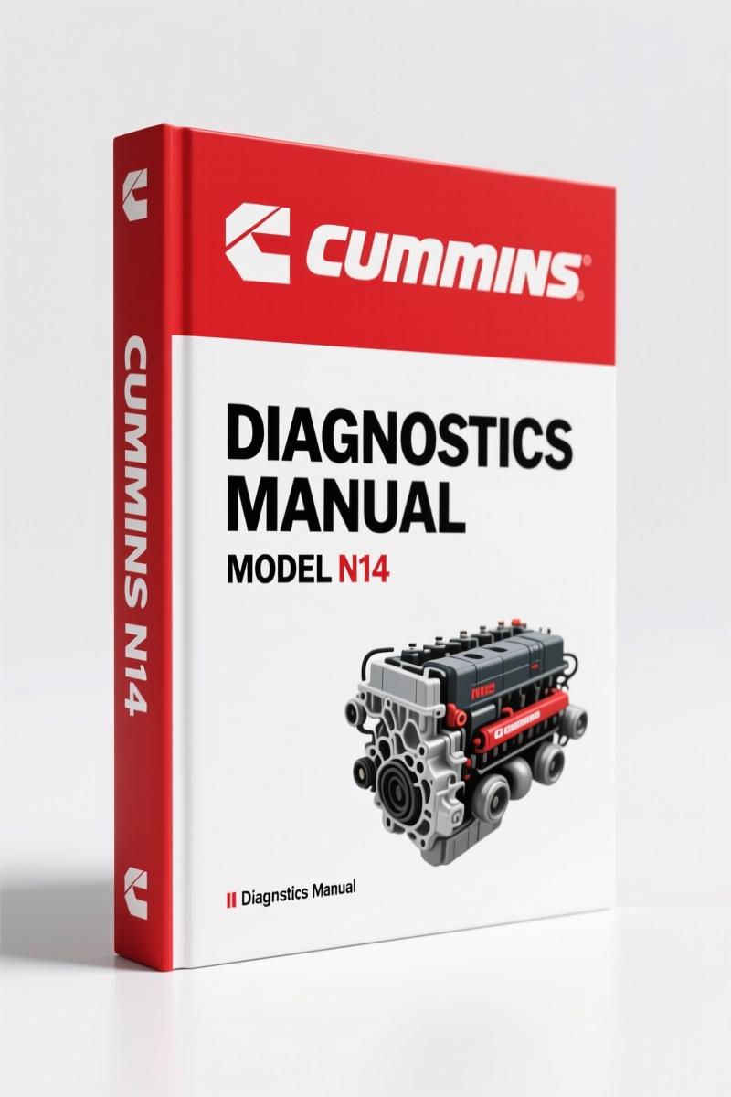
Cummins N14 2001 Diagnostics Manual – 967 Pages of Factory-Certified Service Data
Original price was: $56.80.$40.00Current price is: $40.00.
OEM diagnostics manual for Cummins N14 series (STC, CELECT, CELECT Plus). 967 pages, Spanish, 2001 publication. Covers fuel, electrical, air, and cooling systems.
Description
Cummins N14 2001 Diagnostics Manual – Factory Specs for Techs
If you’re chasing a drivability problem on a Cummins N14 2001 Diagnostics Manual is what you need on your bench. Not a third-party rehash. Not a condensed summary. This is the 967-page bulletin 4017865-00 printed by Cummins in January 2001. It covers the STC, CELECT, and CELECT Plus electronic control systems. You get factory flowcharts, torque tables, and wiring pinouts—data that aftermarket sources routinely get wrong. I’ve seen a shop lose an entire Saturday because a generic manual listed the wrong injector timing. That doesn’t happen with this.
When you open this manual you’re looking at the same content a dealership tech uses. Section i – Introduction covers safety warnings and tool requirements. Section E – Engine Identification tells you how to decode the engine serial number and build date. If you’re dealing with a high-mileage rebuild, you need that. Section TS – Symptom Diagnosis organizes faults by symptom—low power, hard start, smoke—and gives you a logical test tree. No guesswork. No skipping steps.
Engine Identification and Symptom Diagnosis
The first thing you do on any N14 is confirm the model and control system. Section E gives you the location of the dataplate and how to read the CPL (Control Parts List) number. That CPL determines which injectors, which ECM calibration, even which head gasket thickness you use. Get that wrong and you’re pulling the head twice. Section TS then maps common complaints to specific tests. For example, “Engine cranks but will not start” sends you to the fuel system checks in Group 05. No fluff, just cross-referenced page numbers.
What Does the Fuel System Section Cover?
Section 5 – Fuel System (Group 05) and Section 6 – Injectors and Fuel Lines (Group 06) are the heart of this manual. You get the high-pressure pump removal/installation procedure, injector timing specs, and the CELECT fuel control valve test. The manual tells you exactly which special tools you need—Cummins part numbers included. If you’re swapping an injector on a CELECT Plus engine the manual lists the torque sequence for the hold-down clamp. That torque value is different from the mechanical STC model. Don’t guess. For related procedures, see the Cummins N14 Operation and Maintenance Manual for routine service intervals and fluid capacities.
967 Pages of Factory Diagnostics
That page count isn’t padding. It’s broken into 17 main sections plus specifications and component manufacturer data. Section 7 – Lubrication System, Section 8 – Cooling System, Section 9 – Control Units (ECM/CELECT), Section 10 – Air Intake System, Section 11 – Exhaust, Section 12 – Compressed Air (if equipped), Section 13 – Electrical Equipment, Section 14 – Engine Test, Section 16 – Mounting Adaptations, Section 17 – Miscellaneous, and Section 20 – Vehicle Brake System. Every section has torque tables, clearance limits, and diagnostic procedures. Page 73, for instance, has the charge pressure specs for the CELECT system. You don’t have to flip through three different books.
Get the Right Torque Data from Section V
Section V – Specifications is where the money is. All torque values are in foot-pounds and inch-pounds. Main bearing cap bolts, connecting rod bolts, cylinder head bolts—listed by engine model and control type. The head bolt torque on an N14 CELECT Plus is different from the STC because of the higher injection pressure. This manual also gives you the angle-tightening procedure for the head bolts on certain build dates. If you’re doing an in-frame overhaul you need those numbers. Don’t rely on a generic chart. Use the factory spec from this book.
CELECT and CELECT Plus: Control Unit Diagnostics
Section 9 – Control Units covers the ECM, the fuel control actuator, and the wiring harness diagnostics. It includes pinout diagrams for the 28-pin and 50-pin connectors. If the engine has a fault code you can cross-reference it with the diagnostic table in Section 9. The manual also covers the 4510 and 4540 electronic controls for the earlier CELECT systems. For background on how electronic diagnostics evolved, check the On-board Diagnostics (OBD) overview. That context helps when you’re interpreting intermittent fault codes.
Section 13 – Electrical Equipment covers the starter, alternator, and sensors—coolant temperature, oil pressure, and timing reference. The wiring diagrams are complete with wire colors and connector views. If you’re chasing a no-start caused by a bad CMP sensor, the manual gives you the resistance check and voltage readings. No guessing. No swapping parts blindly.
Why This Manual Beats the Aftermarket Copies
I’ve had customers bring in so-called “comprehensive” manuals that skip the injector timing procedure or give the wrong fuel pressure specs. This Cummins factory document is the original. It was printed on January 2001 from bulletin 3666142-00 (the English source), then translated to Spanish for this export edition. The content is exactly what the Cummins field service tool kits reference. Every torque value, every clearance spec, every diagnostic step comes from the engineering group, not some writer guessing from a parts catalog. That matters when you’re 30 minutes into a job and the bolt snaps because the spec was wrong. For mechanical components like the transmission interface, the Manual Transmission section in this manual covers the PTO and clutch housing alignment specs.
If you need the parts breakdown to order components, pair this manual with the Cummins N14 Parts Catalog for exact part numbers. For older rebuild procedures, the Cummins N14 1991 Workshop Manual covers the mechanical STC engines without the electronic controls.
Frequently Asked Questions
- Does this manual cover the CELECT Plus electronic system?
- Yes. The manual explicitly covers STC, CELECT, and CELECT Plus models. Section 9 – Control Units includes the CELECT Plus ECM diagnostics, fuel control actuator tests, and wiring diagrams. The torque specs and test limits in Section V are broken out by control type.
- Can I use this manual for a 1998 N14?
- Check the engine’s CPL number. This manual covers up to January 2001 production. If your engine has CELECT Plus electronics built before that date the information applies. For very early STC engines (pre-1991) the mechanical specs are still valid, but you may need the 1991 Workshop Manual for older service procedures.
You’ve got a customer’s truck down with a fuel system fault. The ECM is throwing code 123. You need the pinout and the test sequence. This manual gives you that in Section 9, then cross-references to Section 5 for fuel pressure specs. No flipping through five books. No calling the dealer. Access the Factory Manual and get the job done right the first time.
Additional information
| Brand | Cummins |
|---|---|
| Language | English |
3 reviews for Cummins N14 2001 Diagnostics Manual – 967 Pages of Factory-Certified Service Data
You may also like…
-
Sale!
Cummins QSB6.7, ISL, ISC, ISB, QSB4.5 2014 Repair Manual – 810 Pages
Original price was: $109.20.$70.00Current price is: $70.00. -
Sale!
Cummins 495, 743, 855, V-1710, KT-1150 Service Manual – 143 Pages
Original price was: $89.70.$65.00Current price is: $65.00. -
Sale!
Cummins NT 855 Service Manual – 693 Pages of OEM Repair Data for Big Cam III & IV
Original price was: $104.00.$65.00Current price is: $65.00. -
Sale!
Cummins ISB, ISBe2, ISBe3, ISBe4, QSB4.5 Troubleshooting Manual
Original price was: $92.30.$65.00Current price is: $65.00.
Related products
-
Sale!

1994 Troubleshooting Manual – International 1000-4000 FBC
Original price was: $60.00.$50.00Current price is: $50.00. -
Sale!
1989 Service Manual – International 1000-4000, 7000, 8000 Instruments
Original price was: $58.80.$40.00Current price is: $40.00. -
Sale!
1996 Operators Manual – International 1000-4000 Series (246 pages)
Original price was: $15.28.$9.99Current price is: $9.99. -
Sale!

2006 Service Manual – International DT 466E, 530E Diesel Engine
Original price was: $67.50.$50.00Current price is: $50.00.
Michael T. –
Excellent quality! The scan is high-quality and well indexed. Every spec sheet is included for Cummins N14. Saved my weekend project! Thank you.
Thomas B. –
Perfect factory service manual. It is easily zoomable on my tablet without losing quality. A must-have for any Cummins N14 owner doing maintenance. Worth every penny.
workshop_guy –
I am extremely satisfied with this transaction. The document looks clean. Every wiring layout is provided for Cummins N14. Saves me a lot of money.