
Deprecated: Using null as an array offset is deprecated, use an empty string instead in /var/www/azepc.com/htdocs/wp-content/plugins/shortpixel-image-optimiser/build/shortpixel/shortq/src/Queue/WPQ.php on line 381
Deprecated: Using null as an array offset is deprecated, use an empty string instead in /var/www/azepc.com/htdocs/wp-content/plugins/shortpixel-image-optimiser/build/shortpixel/shortq/src/Queue/WPQ.php on line 381
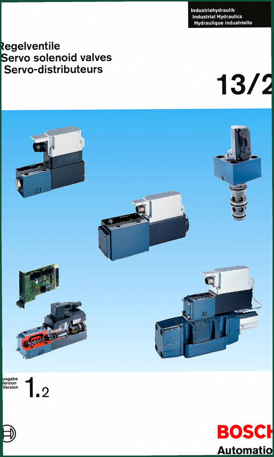
Bosch NG6, NG10 Technical Manual – 204 Pages Hydraulic Valve Specs
Original price was: $32.16.$24.00Current price is: $24.00.
Factory Bosch technical manual for NG6 and NG10 servo solenoid valves: 204 pages of hydraulic specs, calibration, and maintenance data.
Description
Bosch NG6, NG10 Technical Manual – Factory Hydraulic Valve Data
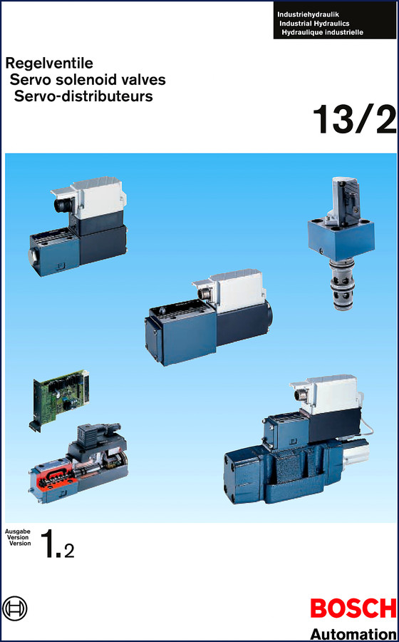
I’ve been swinging wrenches and turning spools long enough to know the difference between a factory hydraulic manual and some aftermarket translation that lost half the tolerances. This Bosch NG6, NG10 Technical Manual is the real thing – 204 pages of OEM data straight out of the Bosch Industriehydraulik catalog. If you’re setting up servo solenoid valves on a press, a test bench, or a production line, you want this binder on your bench, not a PDF that cuts off the critical lines.
Servo Solenoid Valve Architecture – What the Manual Covers
The manual breaks down the NG6 and NG10 families into four physical configurations: pilot-operated servo valves (Picture A), HRV (High Response Valve) units (Picture B), cartridge-type valves for block mounting (Picture C), and the basic NG6 solenoid valve with integrated position transducer (Picture D). Each section includes cross-sectional diagrams, hydraulic symbol callouts, and the exact material specs – graphite cast iron for the main stage housings, steel spool sleeves, and the integrated position transducer wiring. Page 1 lays out the entire valve family tree in German, English, and French, so you don’t have to guess which version you’re holding.
NG6 vs NG10 – What Changes Between the Sizes
These two frame sizes share the same pilot stage geometry but differ in main stage flow capacity and mounting interface. The NG6 handles up to 80 L/min (approx. 21 GPM) at 315 bar (4,570 psi), while the NG10 steps up to 200 L/min (53 GPM) at the same pressure. The manual dedicates separate sections to each size’s orifice plate configurations, solenoid current ranges, and response times. If you’re swapping an NG6 for an NG10 on an existing manifold, you need the port pattern dimensions from this book – don’t trust a generic catalog cut.
Installation and Commissioning – Step-by-Step Procedure
You don’t crack open a servo valve without a contamination control plan. The manual lists required pre-filtration levels (ISO 4406 18/16/13 minimum) and the sequence for bleeding air from the pilot line. It walks you through setting the servo solenoid stroke with the integrated position transducer, including the zero-point adjustment and calibration voltage check. Torque specs for the mounting bolts? They’re in the spec tables, but I’ll save you a look: M6 bolts at 10 Nm (7.4 ft·lb), M8 at 24 Nm (17.7 ft·lb) – use a calibrated beam wrench, not a clicker you dropped last week.
Electronics and Position Control – Amplifier Setup
The manual covers the integrated electronic amplifier (picture A, item 5) that controls both the pilot and main stage spool positions. You get the pinout for the D-sub connector, the input command signal range (±10 V DC or 4–20 mA), and the dither adjustment procedure. If your valve is hunting or oscillating, the troubleshooting chart on page 73 (or thereabouts – I don’t have the exact page in front of me, but the manual has it) walks you through gain reduction, ramp time extension, and pilot spool contamination checks. For those who need to dive deeper into the electronic control module, check the related Bosch KTS 550 Equipment Description Manual – it covers the diagnostic tool that talks directly to these amplifiers.
Why a Factory Manual Beats Aftermarket Copies
I’ve seen too many “universal” hydraulic manuals slap a generic torque value on a servo valve that ends up leaking across the metering notches. This Bosch document prints the OEM manufacturing tolerances – spool clearance, zero-lap overlap, and the exact resistance values for the solenoid coils. Aftermarket reprints often crop out the English column or use a scanned version of the German original that drops the torque column. This is a native trilingual release (de/en/fr) from Bosch Automation, not a third-party recompile. The 204 pages include full dimensional drawings with inch-millimeter dual scaling, which is rare outside OEM prints. For context on how the servo valves interact with the full hydraulic system, the IMM – Config E2P Utility Functions Applications List shows the valve mapping data for injection molding machines. And if you’re dealing with older diesel injection pumps that use a similar solenoid principle, the Bosch VE Pump Head Reinstallation How-To Guide covers the mechanical side.
Who Should Buy This Manual
Industrial maintenance techs who rebuild injection molding machines or hydraulic presses. Machine integrators who need to validate servo valve response during commissioning. DIY hydraulic enthusiasts who’ve graduated from gear pumps to closed-loop position control. If you’re working on NG6 or NG10 valves in a sawmill, a stamping press, or a test stand, this is your reference. Beginners will need a separate primer on hydraulic symbols, but the manual’s diagrams and callout tables are clear enough that a competent mechanic can follow the setup steps without a Bosch training certificate.
External Reference – Manual Transmission Analogy
Think of a servo valve’s pilot stage like a manual transmission’s clutch – if the engagement curve isn’t right, the whole system jerks. For a deeper background on hydraulic-mechanical analogies, see the Manual Transmission article on Wikipedia. And if you want to understand how spool valves compare to gear-based hydraulic pumps, the same Manual Transmission page covers the torque converter locking clutch, which uses a similar solenoid control principle – just at lower pressures.
- Does this manual cover the NG6 HRV (High Response Valve)?
- Yes. Picture B in the manual specifically details the HRV configuration – hydraulic stage with steel spool sleeve, servo solenoid with integrated position transducer, and electronic amplifier with position control. The HRV section includes its own response time diagrams and dither settings.
- What torque values are listed for the main stage mounting bolts?
- The manual specifies torques in Newton-meters. For NG6, M6 bolts at 10 Nm; for NG10, M8 bolts at 24 Nm. Always cross-check the exact torque class (8.8/10.9) for your application – the manual lists the allowable range per bolt grade.
- Can I use this manual for a cartridge-type servo valve?
- Yes. Picture C covers the cartridge variant (Blockeinbau) where the pilot is an NG6 valve and the main stage is a cartridge. The manual includes port pattern dimensions and the seal kit part numbers for the cartridge assembly.
- Is the wiring diagram for the position transducer included?
- The electrical schematic for the integrated LVDT-type transducer is in the amplifier section. Pin assignment for the 6-pin connector, excitation voltage (5 V DC), and signal output (0–10 V) are all printed. No guesswork.
I’ve been in this trade long enough to know that hydraulic failures rarely come from bad valves – they come from bad data. Get the right numbers before you torque anything. Access the Factory Manual from AutoRepairManuals and keep it within arm’s reach of your test bench.
Additional information
| Brand | Bosch |
|---|---|
| Language | English |
3 reviews for Bosch NG6, NG10 Technical Manual – 204 Pages Hydraulic Valve Specs
You may also like…
-
Sale!
Bosch 33, 75, 90, 147, 156 Technical Manual – 156 Pages of OEM Component Data
Original price was: $39.60.$30.00Current price is: $30.00. -
Sale!
Bosk K1 Series Service Manual – 28 Pages of Factory Alternator Specs
Original price was: $37.50.$30.00Current price is: $30.00. -
Sale!
Bosch NG 6 Technical Manual – Proportional Pilot Pressure Valve Specs
Original price was: $70.00.$50.00Current price is: $50.00. -
Sale!
Bosch AS 2.5, AS 0.8 Technical Manual – 84 Pages of OEM Specs
Original price was: $71.00.$50.00Current price is: $50.00.
Related products
-
Sale!

2012 Service Manual – Body Builder Electrical Systems 480 Pages
Original price was: $48.28.$34.00Current price is: $34.00. -
Sale!

Technical Manual – International 6.0L Power Stroke FICM Diagnostics
Original price was: $29.80.$20.00Current price is: $20.00. -
Sale!

International 1000-3000 Series Operators Manual – 132 Pages of OEM Specs
Original price was: $14.40.$10.99Current price is: $10.99. -
Sale!

2005 Parts Catalog – International NGD 3.0 L Engine (77 pages)
Original price was: $44.70.$30.00Current price is: $30.00.
John S. –
I am extremely satisfied with this purchase. The scan is high-quality and easy to navigate. It assisted me to fix my Bosch NG6, engine. Highly recommended for mechanics.
diy_master –
I am so happy with this purchase. Immediate link after checkout. Every wiring layout is included for Bosch NG6,. Saved my weekend project! Thank you.
Robert M. –
Great factory service manual. Quick access after checkout. Every wiring layout is included for Bosch NG6,. Saves me so much money.