
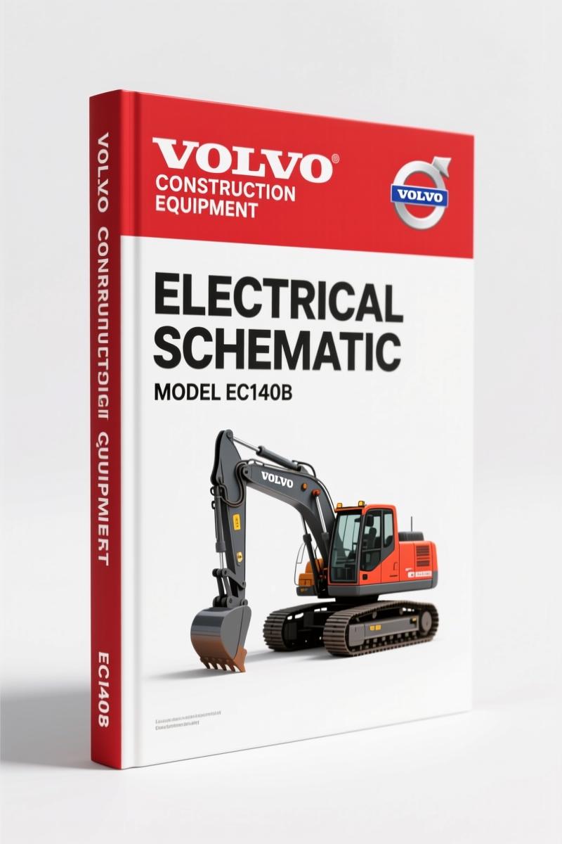
Volvo EC140B Electrical Schematic – 20-Page OEM Wiring Diagram
Original price was: $38.70.$30.00Current price is: $30.00.
20-page factory electrical schematic for Volvo EC140B excavator. Includes engine start circuit, instrument panel, safety relay, and sensor wiring.
Description
If you’re tracing a short on an EC140B and you don’t have the factory electrical schematic, you’re working blind. I’ve seen guys spend half a day chasing a ground fault that this 20-page Volvo Construction Equipment EC140B Electrical Schematic would have shown them in five minutes. This is not some aftermarket redraw — this is the OEM document Volvo printed for their own techs. I don’t trust third-party wiring diagrams on heavy equipment. They miss pin assignments, they guess at wire colors, and they sure as hell don’t have the Safety Start Relay Operation flowchart you get here.
Engine Start and Stop Circuit: Where the Schematic Begins
Page 2 opens with the Engine Start and Stop Circuit diagram. You get the full trace from the VECU safety stop, through the master switch, key switch, battery relay, and into the EMS power relay. The diagram shows the 100A and 80A slow blow fuses, the instrument panel connections, and the DC-DC converter feed. If you’re chasing a no-crank, you start here. The master switch (page 4) and key switch (page 5) have their own dedicated diagrams with terminal identification — B+, BR, R1, R2, C, ACC. I’ve used aftermarket charts that labeled those pins wrong. This schematic gets it right.
7 Critical Sub-Systems in the 05 Electric System – 1 Section
The entire 20-page PDF covers one section: 05 Electric System – 1. That section breaks into 7 sub-systems (if you count each component grouping): Engine Start and Stop, Master Switch, Key Switch, Battery Relay, Safety Start Relay, Safety Limit Switch, Alternator, Slow Blow Fuses, Fuse Box, Instrument Panel, and the sensor cluster — Engine Oil Pressure Switch, Coolant Level Sensor, Coolant Temperature Sensor, Fuel Level Sender, and Air Cleaner Clogging Switch. Every one of those has its own page or sub-page. The Fuel Level Sender circuit on page 17 is a simple two-wire setup, but the resistance values matter — the manual shows the OEM wiring path, not a generic float sender.
What the Safety Start Relay Operation Tells You
The Safety Start Relay is not just a relay — it’s interlocked with the Safety Limit Switch. The schematic shows the relay operation sequence. Without this diagram, you might replace a good relay because you misread the control side. The manual lays out the relay coil path from the key switch through the safety limit switch to ground. If that limit switch is open, the relay won’t pull in, and the engine won’t crank. This is one of those things you’d spend hours diagnosing without the factory diagram. With it, you check the limit switch first.
Get the Right Trace: Key Switch and Battery Relay
The key switch diagram (page 5) shows the switch circuit with five terminals: B+, BR, R1, R2, C, ACC. The battery relay is part of the power distribution. The schematic clarifies that the battery relay is energized when the master switch is on. If you’re getting power at the key switch but nothing downstream, check the battery relay feed. The manual doesn’t assume you know the pinout — it shows you.
Fuel Level Sender and Coolant Temperature Sensor: Factory Wiring Paths
Two sensors commonly fail or get miswired: fuel level sender and coolant temperature sensor. The schematic gives dedicated pages (EC140B-05-16 and EC140B-05-17). The coolant temperature sensor feeds the instrument panel directly — no separate ECU in between on this circuit. The fuel level sender connects to the cluster control. If your gauge reads backwards, you likely swapped the sender wires. The OEM diagram prevents that.
Twenty pages. That’s all.
Who needs this manual? Anyone maintaining a Volvo EC140B excavator — fleet mechanics, owner-operators, rental yards. If you’ve ever had an instrument panel go dark and had to guess which fuse feeds it, this diagram shows the 100A slow blow fuse feeding the cluster control B+. The Instrument Panel circuit (page 11) is clearly laid out. For comparison, aftermarket wiring charts often combine multiple models and omit the safety relay interlock. This manual is specific to the EC140B. Automotive Industry Overview might give you general wiring theory, but this gives you the exact trace.
Source authenticity: This is a direct digital copy of the Volvo Construction Equipment publication. The original file name is VolvoConstructionEquipment_EC140B_Electrical_Schematic_en-76324014703.pdf — that’s the OEM part number. Not a reprint. Not a redrawn copy. The same document Volvo ships to their dealers. Aftermarket manuals? I’ve seen them use a 12-volt symbol on a 24-volt system. No thanks.
- Does this manual cover the entire electrical system of the EC140B?
- It covers section 05 Electric System – 1, which includes the start/stop circuit, master switch, key switch, battery relay, safety start relay and its operation, safety limit switch, alternator, slow blow fuses, fuse box, instrument panel and its operation and circuit, engine oil pressure switch, coolant level sensor, coolant temperature sensor, and fuel level sender. It does not cover the rest of the machine’s electrical systems — those require separate manuals.
- Can I use this to troubleshoot a no-start condition?
- Yes. Follow the Engine Start and Stop Circuit and check the Safety Start Relay operation.
- What format is the manual in?
- Digital PDF, 20 pages. You can zoom in on the diagrams and print them.
- Is this the same document used by Volvo dealers?
- Yes. It is the exact OEM electrical schematic published by Volvo Construction Equipment. Not a reprint or third-party interpretation. The dealer techs use this same diagram.
If you need additional OEM manuals for your Volvo excavator, check out Volvo Construction Equipment EC55B Technical Manual – OEM Hydraulic Cylinder Spe for hydraulic specs. Also, Volvo EC140B Technical Manual – A/C System for Construction Equipment and Volvo EC140B Main Control Valve Diagrams are available for other systems.
Stop working blind. Automotive Wiring guides are fine for cars, but this is heavy equipment. Access the Factory Manual now and keep it on your tablet in the cab.
Additional information
| Brand | Volvo Construction Equipment |
|---|---|
| Language | English |
2 reviews for Volvo EC140B Electrical Schematic – 20-Page OEM Wiring Diagram
You may also like…
-
Sale!
Volvo EC140B Technical Manual – OEM Hydraulic Valve Specs & Diagrams
Original price was: $46.50.$30.00Current price is: $30.00. -
Sale!
Volvo EC140B LC LCM Technical Manual – 24 Pages of Travel Motor Specs
Original price was: $43.50.$30.00Current price is: $30.00. -
Sale!
Volvo EC140B Technical Manual – A/C System Diagnostics
Original price was: $53.20.$35.00Current price is: $35.00. -
Sale!

Volvo EC55B Technical Manual – Hydraulic Cylinder Specs & Repair
Original price was: $36.90.$30.00Current price is: $30.00.
Related products
-
Sale!

1993 Electrical Schematic – International 1000/3000/4000 Bus Chassis OEM Wiring Diagrams
Original price was: $29.26.$22.00Current price is: $22.00. -
Sale!
International 1000-3000 Series Operators Manual – 132 Pages of OEM Specs
Original price was: $14.40.$10.99Current price is: $10.99. -
Sale!
1992 Electrical Schematic – OEM Wiring Diagrams for International 1000-3800
Original price was: $24.48.$18.00Current price is: $18.00. -
Sale!

2011 Parts Catalog – International Truck OE Parts Documentation (1786 Pages)
Original price was: $34.50.$25.00Current price is: $25.00.
Michael T. –
Perfect OEM spec sheet. Quick access after payment. A must-have for any Volvo Construction Equipment EC140B owner doing repairs. Saves me a lot of dollars.
diy_master –
I am very pleased with this purchase. Instant access after payment. A must-have for any Volvo Construction Equipment EC140B DIYer doing maintenance. Saves me hundreds of dollars.