
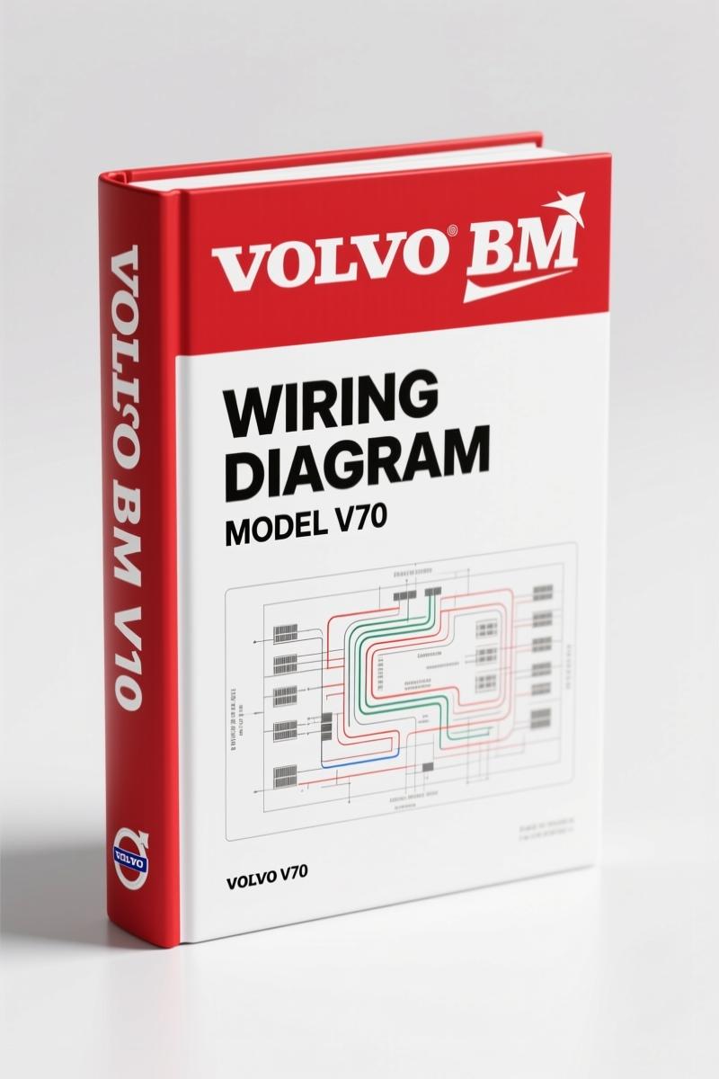
Volvo BM V70, XC70, XC90 Wiring Diagram – 256-Page Factory Electrical Schematics
Original price was: $31.25.$25.00Current price is: $25.00.
Factory wiring diagram for Volvo BM V70, XC70, XC90 2003 models. 256 pages of OEM electrical schematics, fuse maps, and ground connections.
Description
Volvo BM V70, XC70, XC90 Wiring Diagram – 256 Pages of Factory Electrical Data
You have a Volvo BM V70, XC70, or XC90 that’s acting like a Christmas tree with the dash lights, or maybe the starter just quit and you’re chasing a ground that doesn’t exist in the aftermarket diagram you printed off some forum. I’ve been in this business long enough to know that generic wiring schematics are the reason guys smoke modules and fry harnesses. The factory Volvo BM V70, XC70, XC90 Wiring Diagram is the only source you should touch. This 256-page OEM document (TP3964202) covers every circuit, fuse, relay, and control module on the 2003 models. No guesswork, no translation errors from a third-party publisher.
What You Get in These 256 Pages
Page 1 gives you the contents and abbreviations — including a full legend so you don’t mistake a ground symbol for a splice. Then it walks you through how to use the wiring diagram. After that, the electrical distribution overviews for the V70 and XC90 are laid out. You’ll find 13 pages of fuses covering the engine compartment (11A/1‑8 through 11B/11‑23), passenger compartment (11C/1‑38), and cargo compartment (11D/1‑18 plus 11E/1‑7). Relays and shunts get 5 pages: ignition switch, engine bay relays FMA2‑FST3, passenger compartment CMA2‑CSH4, cargo compartment RMA1‑RSH6, and other relays.
Ground connections are indexed by reference numbers 31/1 through 31/98 across 6 pages. Need to locate the ground point for the rear electronic module? It’s in there. Control modules cover 8 pages, with separate overviews for V70/XC70 and XC90, plus pinout diagrams for the Central Electronic Module (CEM) and Rear Electronic Module (REM). The engine management systems for 5‑cyl, 6‑cyl, Bi‑fuel, and diesel engines are grouped under Group 23. Page 2 lists the additional groups: Group 26 (cooling fan), Group 27 (cruise control), Group 32 (power supply), Group 33 (starting system), and Group 35 (lighting — including Bi‑Xenon high/low beams). Towing bracket wiring, diagnostics, 12V outlets, audio systems… it’s all there.
Don’t Trust Aftermarket Wiring Diagrams
I’ve pulled harnesses apart because a Chilton’s diagram said pin 3 was the 12V feed when it was actually the LIN bus. That mistake costs you a CEM. The OEM wiring diagram from Volvo BM uses factory-correct colors, connector views, and splice locations. The abbreviations section on page 1 defines every acronym (e.g., CEM, REM, AEM) so you don’t misinterpret. If you’re working on a V70 that has a no‑crank condition, you can trace the starting system circuit in Group 33 using the exact wire colors and gauge listed. Compare that to an aftermarket book that shows a generic “start circuit” with no fuse numbers — that’s how you blow a 30A fuse and wonder why.
For the DIY mechanic in a home garage, this manual is your safety net. Every time you probe a wire, you should know the expected voltage drop and which fuse feeds it. The factory diagram gives you that. If you’re a beginner, start with the “How to use” section on page 1 — it explains the symbols, the routing of power distribution, and how to read the relay tables. Then move to the electrical distribution overview to see which fuse panel (engine, passenger, or cargo) powers your circuit.
How to Read the Factory Wiring Diagram
Take the XC90 electric cooling fan circuit under Group 26. The diagram shows the fan relay, the temperature sensor signal, and the control module output. You’ll see the fuse number (11B/16) and the relay location (FMA2). If the fan doesn’t come on, you can start at the fuse, check voltage at the relay coil, then verify the ground at 31/44. No guessing. The diagrams use a standardized numbering system: each wire has a label that matches the harness connector. Cross-reference with the control module section to see pin numbers. This is how you avoid shorting the CAN bus with a test light.
For the Automotive Wiring basics, you can brush up on color codes elsewhere, but for this specific Volvo BM, you need the exact factory data. The Automotive Wiring fundamentals won’t tell you that the XC90 uses a separate REM for the rear lights. That’s in this diagram.
3 Reasons You Need This Manual on Your Bench
First: fuse and relay locations are indexed by compartment and number. If you’re troubleshooting a dead parking light on the V70, go to “Parking lights V70/XC70” under Group 35 — it shows the wiring from the headlight switch to fuse 11C/14, then to the bulb. Second: ground connections are listed by location and reference number. Third: the control module pinouts let you verify signals without backprobing and risking a short. One technician I worked with spent four hours diagnosing a no‑start that turned out to be a corroded pin on the CEM. The diagram pin 3 for the starter signal was correct — he had missed it because he was using a generic printout.
Related Manuals You Might Need
If you’re working on a later model, check out the VOLVO V70 XC70 S80 2009 Wiring Diagram”>2009 V70/XC70/S80 wiring diagram. For a deeper dive into component locations, the Volvo V70 XC70 XC90 Electrical Wiring Diagram – Section: List Of Components”>list of components section is helpful. Another related manual is the Volvo XC90 2005 Wiring Diagram”>XC90 2005 wiring diagram if you have an earlier model.
- Does this wiring diagram cover both V70 and XC90?
- Yes. The manual covers the 2003 V70, XC70, and XC90. There are separate overviews for each model, and most sections are split (e.g., “Overview V70” and “Overview XC90”).
- What engine types are included?
- Group 23 lists engine management systems for 5‑cylinder, 6‑cylinder, Bi‑fuel, and diesel engines. The wiring for each is shown with separate diagrams.
- Are the fuse numbers and locations accurate for North American models?
- Yes. This is the factory PDF used by Volvo BM dealers. The fuse designations (e.g., 11A/1‑8) match the actual fuse panels in the vehicle. No aftermarket translation.
- Does it include the audio system wiring?
- Yes. Group 39 covers audio with and without extra amplifier for V70/XC70. The diagrams include the amplifier power, speaker wires, and antenna connections.
Access the Factory Manual now. You’ll get a searchable PDF that you can pull up on your tablet or print the pages you need. Every circuit, every connector, every ground point is where Volvo BM engineered it. Stop chasing ghosts with generic crap. Get the real thing.
Additional information
| Brand | Volvo BM |
|---|---|
| Language | English |
3 reviews for Volvo BM V70, XC70, XC90 Wiring Diagram – 256-Page Factory Electrical Schematics
You may also like…
-
Sale!

Volvo BM L120D Service Manual – 603 Pages Factory OEM Documentation
Original price was: $64.35.$45.00Current price is: $45.00. -
Sale!

Volvo BM VN, VHD Service Manual – 104 Pages Factory Preventive Maintenance
Original price was: $60.80.$40.00Current price is: $40.00. -
Sale!

Volvo BM 4600 1984 Parts Catalog – OEM Factory Parts Identification
Original price was: $70.20.$45.00Current price is: $45.00. -
Sale!

Volvo BM P1800 Service Manual – 220 Pages Factory OEM Specs
Original price was: $49.60.$40.00Current price is: $40.00.
Related products
-
Sale!

1993 Operators Manual – International Bus 1000-3000 OEM Specs
Original price was: $12.30.$7.99Current price is: $7.99. -
Sale!

1989 Service Manual – International 2000-8000 Electrical Systems
Original price was: $72.00.$50.00Current price is: $50.00. -
Sale!
International 1000-3000 Series Operators Manual – 132 Pages of OEM Specs
Original price was: $14.40.$10.99Current price is: $10.99. -
Sale!
1995 Operators Manual – International 1000-4000 Series | OEM Documentation
Original price was: $12.49.$9.99Current price is: $9.99.
Charles W. –
This is just what I required. The pages are clean and well indexed. Contains clear bolt torque specs for Volvo BM. Worth every penny.
diy_master –
I am extremely satisfied with this manual. The document looks clean. A must-have for any Volvo BM BM mechanic doing maintenance. I will definitely buy again.
Richard G. –
Great OEM spec sheet. The text is searchable and easy to navigate. A must-have for any Volvo BM BM owner doing maintenance. Great value for money.