
Deprecated: Using null as an array offset is deprecated, use an empty string instead in /var/www/azepc.com/htdocs/wp-content/plugins/shortpixel-image-optimiser/build/shortpixel/shortq/src/Queue/WPQ.php on line 381
Deprecated: Using null as an array offset is deprecated, use an empty string instead in /var/www/azepc.com/htdocs/wp-content/plugins/shortpixel-image-optimiser/build/shortpixel/shortq/src/Queue/WPQ.php on line 381
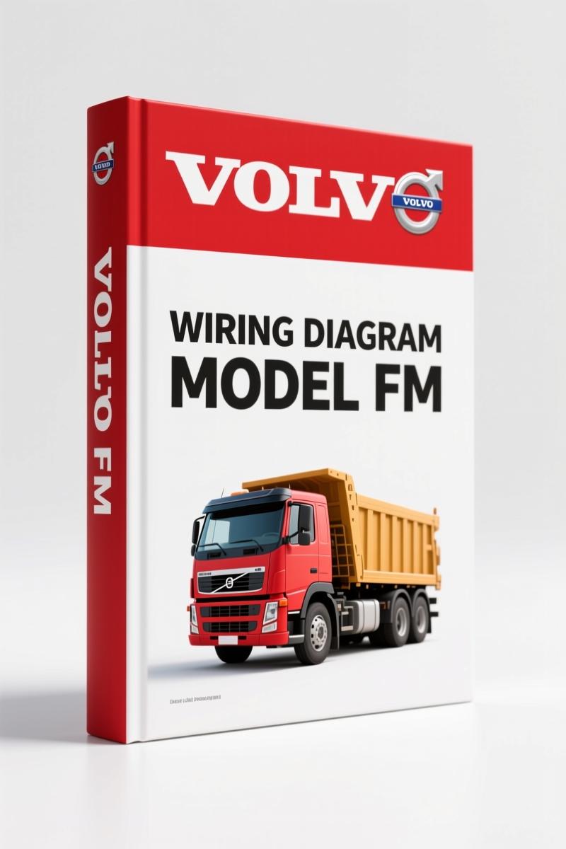
Volvo BM FM Wiring Diagram – 300-Page Factory Electrical Schematics
Original price was: $38.00.$25.00Current price is: $25.00.
300-page factory wiring diagram for Volvo BM FM, covering component diagrams, fuses, relays, connectors, harness layout, and ground connections.
Description
Volvo BM FM Wiring Diagram – Factory Electrical Schematics for the FM
Volvo BM FM Wiring Diagram – if you’re a mechanic who has spent an afternoon chasing a phantom short on an FM, you know the difference between a real factory diagram and some aftermarket mess. That cheap PDF from a forum can land you with a fried ECU or a cab fire. This is the real thing: an OEM document from Volvo Truck Corporation, scanned from the original 2013 publication. 300 pages of wire colors, connector locations, and circuit paths that match what’s actually in the truck.
300 Pages of Factory Wiring Data
Every page in this manual was printed by Volvo, for Volvo techs. The Wiring diagram covers CHID ranges A752768-, B672197-, D200019-, and E808718-. That means it spans multiple production years and chassis configurations. You get the Component wiring diagram index starting on page 1, Fuses on page 221, Relays on page 224, and Ground connections on page 232. No generic summaries. No guesses.
Fuses, Relays, and Ground Connections – Where to Look
When a power window stops working, where do you start? The Fuses section on page 221 is your first stop. It lists each fuse by amperage and circuit. That’s followed by Relays on page 224 – not just location but pin numbers. Ground connection locations on page 232 tell you exactly which bolt to clean. If you jump to the List of connectors on page 233, you can cross-reference the connector numbers to the wiring harness layout on page 230. That’s the difference between a 20-minute fix and a 3-hour wild goose chase.
FRC (A01) Connectors: Why Aftermarket Diagrams Fail
The FRC (A01) connectors section on page 226 is where aftermarket diagrams fall apart. Those 40-pin connectors have specific cavity assignments, and aftermarket drawings often swap two wires. This manual gives you the OEM pinout. You’ll also find the Wiring harness layout on page 230 – drawn to scale with grommet locations and splice points. If you need to pull a harness, you see exactly where it routes behind the dash or down the frame rail.
Use the Wiring Harness Layout Section
Page 230 shows the physical routing of every harness in the cab and chassis. You can see where the main loom branches off for the engine interface (page 18) and where the VMCU, Vehicle Master Control Unit (page 13) connects. That’s critical when you’re installing aftermarket equipment or repairing chafed wires. Don’t trust a generic diagram that says “harness goes left.” This book shows you exactly where it goes.
Cable Colour Code and Abbreviations – Not Optional
Page 293 lists the cable colour codes used throughout the FM. The 291–292 sections cover abbreviations. Volvo uses specific codes like “SB” for black and “R” for red – but they also have two-letter codes for striped wires. If you misread a stripe code on a 12-volt circuit, you can backfeed the wrong module. The factory manual makes these codes explicit with examples. No interpretation needed.
One more thing: this is not a reprint of a copy of a copy. It’s a direct scan from the Volvo Truck Corporation original. The Foreword on page 2 reminds you to always check the latest info at their wiring diagrams site. That’s because Volvo updates these documents. But for any FM built between the listed CHID ranges, this PDF matches the factory configuration.
For related manuals, check out Volvo FH FM Pneumatic Brake Circuit Diagram”>Volvo FH FM Pneumatic Brake Circuit Diagram, the Volvo FM Wiring Diagram”>Volvo FM Wiring Diagram, and the VOLVO FM FH Wiring Diagram”>VOLVO FM FH Wiring Diagram. For deeper understanding of electrical diagnostics, reference Automotive Wiring”>Automotive Wiring basics and Automotive Wiring”>Automotive Wiring troubleshooting.
- Does this manual cover the engine wiring for the D13?
- Yes. The Engine D13, EM-EC01 diagram starts on page 24. Page 24 shows the full EM-EC01 layout. Engine interface diagrams are on pages 18–19.
- Will this work for a 2010 FM with CHID below the listed ranges?
- The manual explicitly lists CHID A752768- (and others). If your FM has a CHID below that starting number, the wiring layout may differ. Volvo updated the harness architecture around that break. This manual covers only the CHID ranges listed on page 1. Always verify your chassis number before relying on any diagram. Missing that step can lead to a misread circuit and a fried component. The factory manual gives you the exact pinout for those specific builds, but it won’t cover earlier or later revisions. If your truck falls outside the range, find the manual that matches your CHID.
Access the Factory Manual from AutoRepairManuals and put the right diagram on your bench. Your multimeter will thank you.
Additional information
| Brand | Volvo BM |
|---|---|
| Language | English |
4 reviews for Volvo BM FM Wiring Diagram – 300-Page Factory Electrical Schematics
You may also like…
-
Sale!

Volvo BM L120D Service Manual – 603 Pages Factory OEM Documentation
Original price was: $64.35.$45.00Current price is: $45.00. -
Sale!

Volvo BM VN, VHD Service Manual – 104 Pages Factory Preventive Maintenance
Original price was: $60.80.$40.00Current price is: $40.00. -
Sale!

Volvo BM P1800 Service Manual – 220 Pages Factory OEM Specs
Original price was: $49.60.$40.00Current price is: $40.00. -
Sale!

Volvo BM 4600 1984 Parts Catalog – OEM Factory Parts Identification
Original price was: $70.20.$45.00Current price is: $45.00.
Related products
-
Sale!

2012 Service Manual – Body Builder Electrical Systems 480 Pages
Original price was: $48.28.$34.00Current price is: $34.00. -
Sale!

1991 Electrical Schematic – 112-Page OEM Wiring Diagram for International 1000-3000 Series
Original price was: $22.75.$17.50Current price is: $17.50. -
Sale!
1993 Operators Manual – International Bus 1000-3000 OEM Specs
Original price was: $12.30.$7.99Current price is: $7.99. -
Sale!

2011 Parts Catalog – International Truck OE Parts Documentation (1786 Pages)
Original price was: $34.50.$25.00Current price is: $25.00.
William H. –
Excellent quality! The PDF looks clean. A must-have for any Volvo BM BM mechanic doing maintenance. I will definitely buy again.
workshop_guy –
I am very pleased with this transaction. The pages are clean and easy to navigate. Contains clear bolt torque specs for Volvo BM. Saved my weekend project! Thank you.
James L. –
This is just what I needed. The PDF is very clear. A must-have for any Volvo BM BM DIYer doing repairs. Saves me hundreds of money.
gearhead88 –
This is exactly what I required. The pages are clean and easy to navigate. Contains clear wiring diagrams for Volvo BM. I will recommend this shop to others.