
Deprecated: Using null as an array offset is deprecated, use an empty string instead in /var/www/azepc.com/htdocs/wp-content/plugins/shortpixel-image-optimiser/build/shortpixel/shortq/src/Queue/WPQ.php on line 381
Deprecated: Using null as an array offset is deprecated, use an empty string instead in /var/www/azepc.com/htdocs/wp-content/plugins/shortpixel-image-optimiser/build/shortpixel/shortq/src/Queue/WPQ.php on line 381
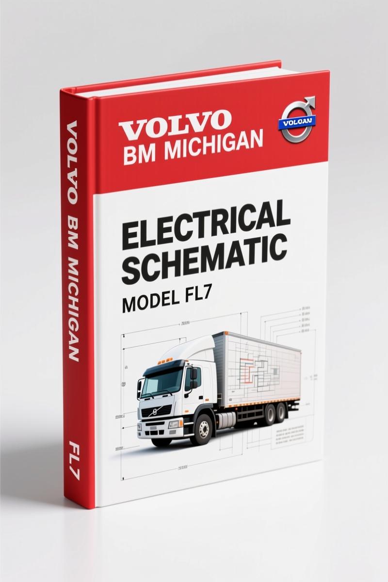
Volvo BM FL7, FL10 Wiring Diagram – Factory Electrical Schematics
Original price was: $38.25.$25.00Current price is: $25.00.
138-page factory wiring diagram for Volvo BM FL7 and FL10 trucks. OEM electrical schematics with component index, fuse layout, and color codes.
Description
Volvo BM FL7, FL10 Wiring Diagram – Factory Electrical Guide
If you’ve ever chased a short in a Volvo BM FL7 or FL10 without the factory wiring diagram, you know the feeling. Half the day gone, a multimeter in one hand, and a guess in the other. The Volvo BM FL7, FL10 Wiring Diagram from AutoRepairManuals puts an end to that. This is the same document Volvo Truck Corporation issued for their service network — not a scanned reprint from some third party that lost half the contrast. 138 pages, factory-original, straight from the OEM.
Volvo BM FL7, FL10 Wiring Diagram: Factory Layout and Index
Page 1 starts with a foreword from Volvo noting that procedures are based on designs up to May 1996, and that supplementary bulletins will update the manual. That’s honest engineering — they know things change. The component wiring diagram index on page 2 lists every circuit you’ll need: starter motor/alternator at 24 V, coolant level, preheating, exhaust pressure governor, exhaust brake, range inhibitor, interval wiping, engine shut-off, speed limiter, EDC (electronically controlled fuel injection) with variants for MGS, AGS, and Powertronic, parking lights, dipped beams, fog lights, brake lights, direction indicators, voltage converter, reversing lights, loading light, fifth wheel light, rear fog lights, rotating warning light, interior lights, cigarette lighter, horn, reverse warner, windscreen wipers and washers, headlamp wipers and washers, climate unit (air conditioning) with CU-ACAUT, CU-ACMAN, CU-HEAT, parking heater DW80, and heated seat. That is not a summary — that is the actual table of contents. You get every circuit, every option, every page reference.
What the Component Wiring Diagrams Cover
Starting on page 6, the actual wiring diagrams show each system individually. Need the EDC wiring for a Powertronic? Page 9. Need the brake light circuit for an Australian (AUS) variant? Page 12. The diagrams are laid out with component labels, wire colours, and connector pin numbers. Volvo BM FE 2007 Wiring Diagram – Factory OEM Manual (190 Pages) follows the same Volvo standard, so if you work on later trucks, cross-referencing is straightforward.
Circuit Board (32) Electrical Centre – Fuses and Relays
Page 114 shows the circuit board (32) electrical centre layout. Pages 116 and 117 list every fuse and relay on that board — amperage, position, function. If you’ve ever pulled the wrong fuse because an aftermarket manual said “check fuse 15” and it was actually fuse 13, you understand why factory data matters. Page 118 covers the 6-unit fuse holder for auxiliary circuits. This section alone saves you from fried modules.
138 Pages of OEM Electrical Specs
Volume is not the point — accuracy is. 138 pages means every harness, every connector, every splice point is documented. The cable harness illustration index starts on page 119, followed by the list of connectors (page 122) and list of components (page 128). Abbreviations on page 133 decode every acronym Volvo used. Cable colour code on page 134 gives you the solid and stripe patterns — e.g., SB is black, SR is red, SB/SR is black with red tracer. Without that code, you are guessing which wire carries the ignition feed versus the parking light circuit. Volvo BM XC90 2009 Wiring Diagram – OEM Factory Specs uses the same colour-coding philosophy, but for a different platform. For those working on older Volvo BM equipment, Volvo BM XC90 2005 Wiring Diagram – Factory OEM Electrical Manual is also in the collection.
Understand the Cable Colour Code Before You Splice
Page 134 lists the full cable colour code. Do not start cutting wires without it. One misidentified ground wire can backfeed through a control unit and cost you a day of diagnostics and a $400 module. Volvo used a consistent code: SB (black) for ground, SR (red) for 24 V supply, SB/SR (black/red) for switched power. The manual also includes a “B = Contact extra exhaust brake (RHD)” note on page 7 — factory-level detail that aftermarket diagrams never capture. For general background on reading vehicle wiring, Automotive Wiring can supplement your knowledge, but nothing replaces the OEM document.
Source Validity – Factory Volvo vs Aftermarket Trash
I have seen aftermarket wiring diagrams that show a relay where Volvo put a resistor, or swap pin 1 and pin 3 on a connector. That gets expensive. This manual is an official Volvo Truck Corporation publication for the FL7 and FL10 (LHD, CHID A246776-). It includes the warning levels Volvo uses — Note, Important, Caution, Warning, Danger — and the original copyright. No third-party re-labeling. No fuzzy scans. If you need to trace a circuit under the dash of an FL7, this is the map you want.
- Does this wiring diagram cover the EDC engine control system for both MGS and Powertronic variants?
- Yes. Page 9 lists three EDC variants: H = MGS, J = AGS, P = Powertronic. Each has its own wiring diagram within the manual. The MGS and AGS are earlier electromechanical controls; Powertronic is the full electronic injection. All three are included.
- What is the difference between this and a generic wiring book?
- This is the actual Volvo factory document. Generic books guess wire colours and omit option codes like “A = AUS” for Australian lighting or “B = Contact extra exhaust brake (RHD)”.
You need to fix an FL7 or FL10 electrical problem? Stop wasting time with aftermarket PDFs that put a 12 V symbol on a 24 V system. Access the Factory Manual from AutoRepairManuals. It’s the same binder Volvo handed to their dealers. 138 pages, OEM colour codes, fuse layouts, and connector pinouts. Your multimeter will thank you.
Additional information
| Brand | Volvo BM |
|---|---|
| Language | English |
2 reviews for Volvo BM FL7, FL10 Wiring Diagram – Factory Electrical Schematics
You may also like…
-
Sale!

Volvo BM VN, VHD Service Manual – 104 Pages Factory Preventive Maintenance
Original price was: $60.80.$40.00Current price is: $40.00. -
Sale!

Volvo BM L120D Service Manual – 603 Pages Factory OEM Documentation
Original price was: $64.35.$45.00Current price is: $45.00. -
Sale!

Volvo BM 4600 1984 Parts Catalog – OEM Factory Parts Identification
Original price was: $70.20.$45.00Current price is: $45.00. -
Sale!

Volvo BM P1800 Service Manual – 220 Pages Factory OEM Specs
Original price was: $49.60.$40.00Current price is: $40.00.
Related products
-
Sale!

Acura NSX 1991 Service Manual – 1420 Pages OEM
Original price was: $102.05.$65.00Current price is: $65.00. -
Sale!

Service Manual – International HS 2.8L Engine – 130 Pages of Factory Specs
Original price was: $56.40.$40.00Current price is: $40.00. -
Sale!

1993 Electrical Schematic – International 1000/3000/4000 Bus Chassis OEM Wiring Diagrams
Original price was: $29.26.$22.00Current price is: $22.00. -
Sale!

2005 Parts Catalog – International NGD 3.0 L Engine (77 pages)
Original price was: $44.70.$30.00Current price is: $30.00.
John S. –
This is just what I was looking for. It is very easy to read on my laptop without losing quality. It helped me to fix my Volvo BM BM electrical system. Saves me so much money.
Thomas B. –
I am very pleased with this purchase. The text is searchable and well indexed. Contains detailed wiring diagrams for Volvo BM. Saved my weekend project! Thanks.