
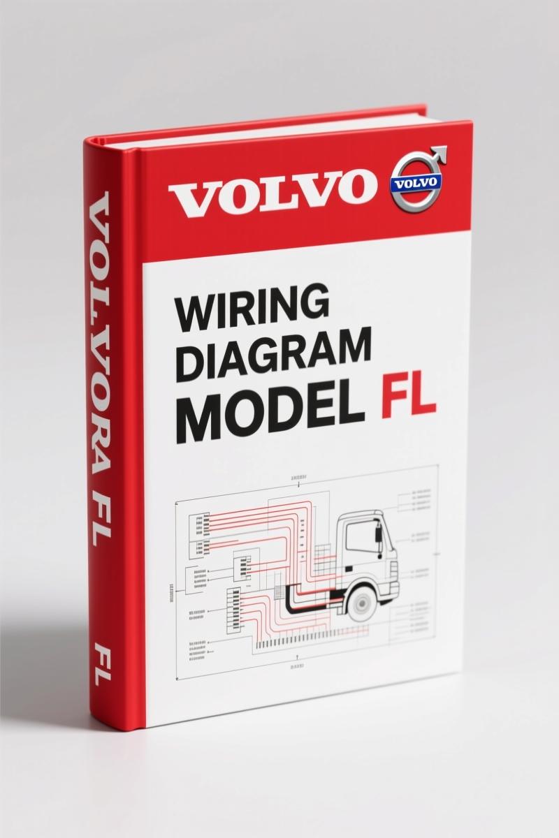
Volvo BM FL Wiring Diagram – Factory Electrical Schematics for FL
Original price was: $64.00.$40.00Current price is: $40.00.
190-page factory wiring diagram for Volvo BM FL. Includes component wiring diagrams, fuse/relay locations, connector lists, and ground connections.
Description
Volvo BM FL Wiring Diagram – Factory OEM Electrical Manual
I’ve been turning wrenches for nearly three decades, and nothing slows a job down faster than chasing a short with a generic diagram that doesn’t match the harness. The Volvo BM FL Wiring Diagram is the real deal – a factory OEM publication, 190 pages long, pulled straight from Volvo’s engineering files. This isn’t a third-party rehash. Every wire number, every connector pin, every ground point comes from the same source the dealer techs use. If you’re working on an FL truck or machine and need to trace a circuit, this is the only document you should trust.
190 Pages of Wiring Schematics
At 190 pages, this manual covers the complete electrical system for the FL. The TOC starts with an Example of wiring diagram that shows how to read the numbering system – you’ll see the starting switch, wiring numbers, and component labels. Then it moves into the real meat: Component wiring diagram index followed by Component wiring diagrams starting on page 8. Each component gets its own schematic, so you’re not flipping through generic layouts. Need the fuse layout? Page 124. Relay locations? Page 127. Want to find every ground connection? The Ground connections section on page 132 includes a full list.
Component Wiring Diagrams: What’s Covered
The Component wiring diagrams section (pages 8–77) is the heart of this manual. Every major electrical component in the FL is represented: the starting switch, instrument cluster, lighting circuits, engine control modules, transmission controls, and auxiliary systems. Each diagram uses Volvo’s own wire numbering scheme, so you can trace a specific circuit from the battery to the load without guessing. The List of wiring numbers at the back cross-references every number to its function – a lifesaver when you’re staring at a bundle of twenty wires and need to identify pin 13 on XJC01_03.
Fuses and Relays: Page 124 and 127
Blown a fuse and can’t find the map? The Fuses section on page 124 gives you the exact location of every fuse in the FL, plus amp rating and circuit assignment. Same for relays on page 127 – you get the relay number, function, and which connector it plugs into. No aftermarket misinterpretation. This is factory data, period. If the manual says relay XACR01 controls the auxiliary heater fan, that’s what it controls. I’ve had guys waste half a day because a cheap aftermarket diagram showed the wrong relay pinout. Don’t be that guy.
Connector List: 50+ Connectors Mapped
The List of connectors section is a goldmine. It covers over 50 connectors by their factory codes – PB3, X02, X03, XACC11 (PB1), XACC12 (PB2), all the way through XT62 and XT65. Each entry tells you the connector type, cavity count, and which wires go to which pin. For example, connector XJC01_07 links to the cab interior harness. You can see the exact wire colors and destinations. This level of detail is why I tell every apprentice to stop using generic wiring guides and buy the OEM manual. The difference in accuracy is the difference between a repair that holds up and one that comes back on a tow truck.
Ground Connections: Where to Find Them
Bad grounds cause more electrical issues than dead components. The manual devotes the Ground connections section (page 132) to listing every ground point on the FL – frame grounds, engine block grounds, cab grounds. It includes a List of ground connections with exact locations and what each ground serves. If your FL’s starting switch is intermittent, the first thing I’d check is ground XJC40 behind the left kick panel. The diagram shows you exactly where it bolts and how to test it.
Who Needs This Manual
DIY mechanics and home garage enthusiasts who own a Volvo BM FL – whether it’s a loader, truck, or industrial machine – need this manual if you plan to diagnose or repair any electrical circuit. Professional mechanics working in a shop that sees Volvo BM equipment will cut their diagnostic time in half with factory schematics. Workshop owners: having this on the bench means your techs aren’t guessing, which reduces comeback liability. It’s the same manual that came with the vehicle from the factory – no shortcuts, no reprints.
Why OEM Beats Aftermarket
Aftermarket wiring diagrams copy from each other, introduce errors, and often leave out critical notes like wire gauge and splice locations. This manual is an original Volvo Truck Corporation publication, printed from the same source as the dealer service system. The foreword on page 2 includes the standard warnings and cautions – Volvo doesn’t play with safety. Using OEM documentation means you get the exact connector designations and harness routing that the engineers intended. I’ve seen too many aftermarket diagrams show a wire going to a pin that doesn’t exist in the real harness. That doesn’t happen here. For related manuals, check out the Volvo BM FE 2007 Wiring Diagram – Factory OEM Manual (190 Pages) or the Volvo BM XC90 2009 Wiring Diagram – OEM Factory Specs and Volvo BM XC90 2005 Wiring Diagram – Factory OEM Electrical Manual if you work on those models. For general information on Automotive Wiring practices, Wikipedia has decent basics, but for this specific machine, stick with factory data. Another external resource on Automotive Wiring principles can help beginners understand circuit theory, but never use it to replace the actual schematic.
- Q: Is this manual specific to the Volvo BM FL model?
- Yes, it covers only the FL series from Volvo BM. No generic cross-model content.
- Q: How are connectors listed? I see many X codes in the TOC.
- Connectors are listed by factory codes like XACC11, XJC01_03, and XT56_B. The manual provides a full list of connectors with pin assignments, wire numbers, and cavity counts. For instance, connector XJC01_07 has 18 cavities and connects the cab interior harness. You get the exact wire color for each pin, so you can back-probe or replace without cutting into the harness. The list covers over 50 unique connectors, each identified by its Volvo part number. This is the level of detail aftermarket manuals skip. If you need to troubleshoot a starting switch circuit, you’ll find the connector X02 directly linked to the switch on the component diagram.
If you’re serious about fixing the electrical system on your Volvo BM FL without chasing phantom problems, you need this factory wiring diagram on your bench. It’s 190 pages of verified OEM data – fuses, relays, connectors, ground points, and every wire number matched to its component. Access the Factory Manual and stop wasting time with half-assed schematics.
Additional information
| Brand | Volvo BM |
|---|---|
| Language | English |
2 reviews for Volvo BM FL Wiring Diagram – Factory Electrical Schematics for FL
You may also like…
-
Sale!

Volvo BM 4600 1984 Parts Catalog – OEM Factory Parts Identification
Original price was: $70.20.$45.00Current price is: $45.00. -
Sale!

Volvo BM L120D Service Manual – 603 Pages Factory OEM Documentation
Original price was: $64.35.$45.00Current price is: $45.00. -
Sale!

Volvo BM P1800 Service Manual – 220 Pages Factory OEM Specs
Original price was: $49.60.$40.00Current price is: $40.00. -
Sale!

Volvo BM VN, VHD Service Manual – 104 Pages Factory Preventive Maintenance
Original price was: $60.80.$40.00Current price is: $40.00.
Related products
-
Sale!

1993 Electrical Schematic – International 1000/3000/4000 Bus Chassis OEM Wiring Diagrams
Original price was: $29.26.$22.00Current price is: $22.00. -
Sale!
1993 Operators Manual – International Bus 1000-3000 OEM Specs
Original price was: $12.30.$7.99Current price is: $7.99. -
Sale!
International 1000-3000 Series Operators Manual – 132 Pages of OEM Specs
Original price was: $14.40.$10.99Current price is: $10.99. -
Sale!

2005 Parts Catalog – International NGD 3.0 L Engine (77 pages)
Original price was: $44.70.$30.00Current price is: $30.00.
James L. –
Great buy! The text is searchable and easy to navigate. A must-have for any Volvo BM BM owner doing repairs. Worth every penny.
Michael T. –
This is just what I needed. Quick access after checkout process. Contains clear schematics for Volvo BM. Saved my weekend project! Thanks.