
Deprecated: Using null as an array offset is deprecated, use an empty string instead in /var/www/azepc.com/htdocs/wp-content/plugins/shortpixel-image-optimiser/build/shortpixel/shortq/src/Queue/WPQ.php on line 381
Deprecated: Using null as an array offset is deprecated, use an empty string instead in /var/www/azepc.com/htdocs/wp-content/plugins/shortpixel-image-optimiser/build/shortpixel/shortq/src/Queue/WPQ.php on line 381
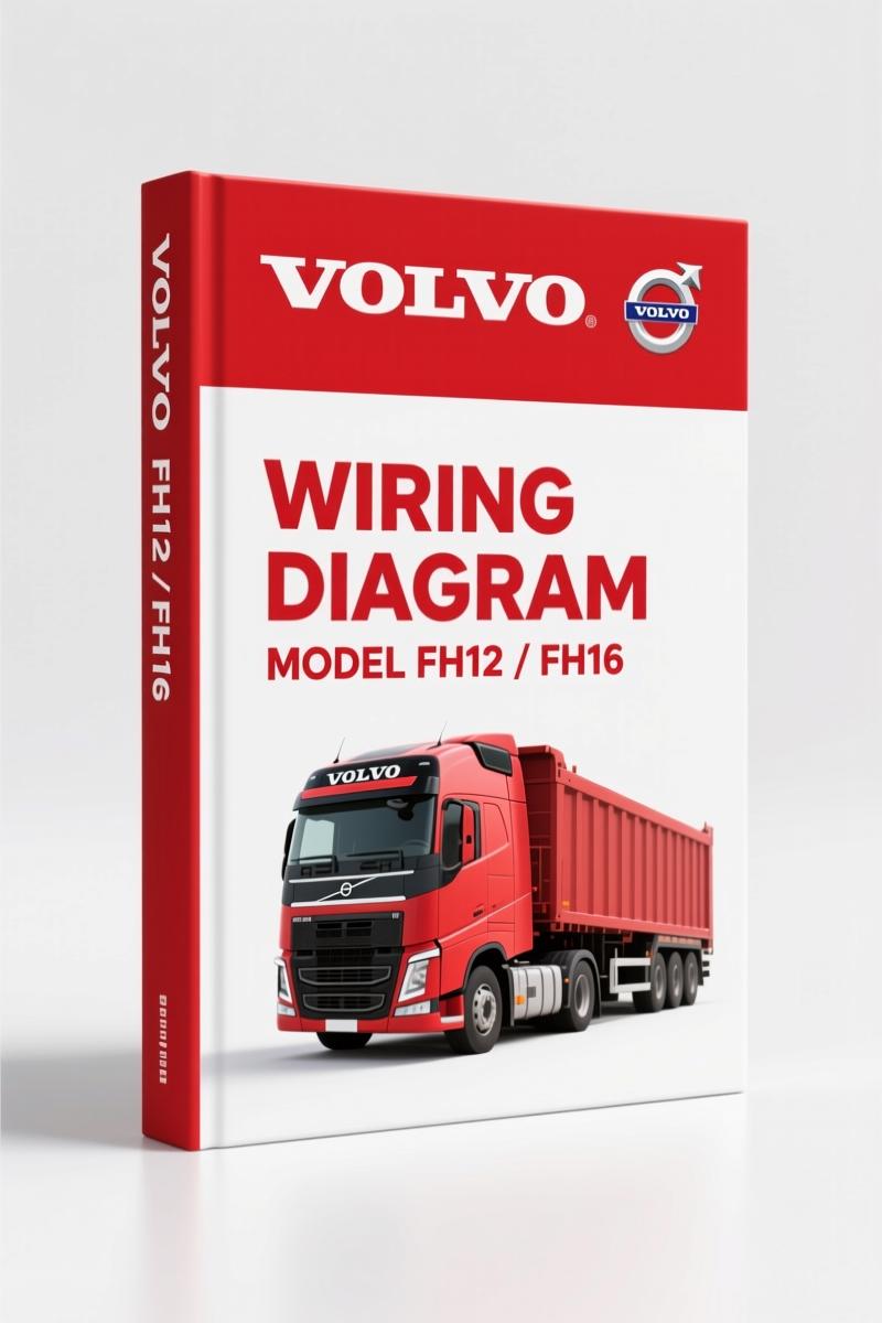
Volvo BM FH12 FH16 Wiring Diagram – Factory Electrical Schematics
Original price was: $43.50.$30.00Current price is: $30.00.
Factory wiring diagram for Volvo BM FH12/FH16: 134 pages of electrical schematics, fuse/relay maps, connectors, and cable colour codes.
Description
Volvo BM FH12, FH16 Wiring Diagram – Factory Manual, Not a Guess
If you are chasing a short in a Volvo BM FH12, FH16 Wiring Diagram and you are working off a chinese copy or a photocopy that has lost half the pin labels, stop. I have pulled harnesses out of trucks where somebody used a generic diagram and melted a brand new ECU. This 134-page OEM document is what Volvo Truck Corporation put together for trucks from chassis number 254453 onward. It is not a reprint, not a summary. It is the actual factory wiring diagram with every connector, every relay socket, every fuse position, and the exact cable colour code Volvo used. You want to fix it right the first time? Start here.
Component Wiring Diagrams: Where the Real Work Starts
The manual opens with a Component wiring diagram index that points you straight to the system you need. Page 4 kicks off the actual diagrams. These are factory schematics – not redrawn, not simplified. Each wire has a colour code that matches the cable colour code table on page 129. I have used these diagrams to trace a parking brake warning light fault on an FH16 that three other shops had given up on. It took me 20 minutes once I had the right drawing. You do not need to guess which pin is power and which is ground – it is all there.
Circuit Board (32) Electrical Centre: Fuses and Relays Mapped
One of the most useful sections is the coverage of the electrical centre – circuit board (32). Pages 108 through 111 give you the fuse layout and the relay positions. This is where most blown fuses get misdiagnosed because people pull the wrong relay. The manual shows you exactly which relay controls what. For example, the Relays on circuit board (32) electrical centre lists each relay by number and function. If your FH12 loses the brake lights and you think it is a relay, you check page 111 first. That saves you pulling the wrong unit and chasing a ghost.
Cable Colour Code: Why a Generic List Will Burn You
Page 129 contains the Cable colour code. I have seen aftermarket wiring diagrams that use a standard colour scheme – then try to apply it to Volvo harnesses. Volvo has its own code. For example, what they call “GN” might be green/black stripe, not just green. The manual spells out each abbreviation and the exact stripe pattern. If you ignore this and go by eye, you WILL backfeed a circuit and fry a controller. I have seen it happen on an FH16 transmission control unit. Three thousand dollars in damage because a mechanic thought “blue wire” meant the same thing on every truck. It does not.
List of Connectors and Components: Matching Pins Without Guessing
Pages 115 through 127 give you a List of connectors and a List of components. This is not a vague overview. Each connector is listed with its location in the cab or chassis, the number of pins, and the pin assignments. The component list includes every sensor, solenoid, control unit, and switch that appears in the wiring diagrams. If you are troubleshooting an ABS fault on an FH12 and need to know which pin on the ECU sends wheel speed data, you look up the component, find the connector number, then cross-reference to the diagram. No guesswork. Combine this with the Cable harness illustration index starting on page 112, and you can physically locate the harness branch in the truck.
Does This Manual Cover All FH12 and FH16 Variants?
This manual covers FH12 and FH16 LHD trucks from chassis number 254453 onward, produced up to March 1996 per the foreword. If you have a later model, you need the updated supplement. But for the trucks in that range, it is complete. The index on page 3 lists exactly which systems are covered: component wiring diagrams, illustrations, circuit board details, fuses, relays, cable harnesses, connectors, components, abbreviations, and the colour code. Everything a technician needs to diagnose an electrical problem without a scan tool – although you should still use a good multimeter and a test light.
OEM Document vs Aftermarket Copies: One Has the Factory Specification
What you are buying here is the original Volvo Truck Corporation publication TSP23708/1. It is a scan of the factory manual, not a third-party rewrite. The warnings are Volvo’s own – they use the same level system (Note, Caution, Warning, Danger) that every Volvo dealer tech works from. Aftermarket diagrams leave out the fine print, like which circuits have permanent power even with the key off. This manual shows you. That is why I keep a copy in my shop for the old Scandinavian trucks that roll through. You can cross-reference it with other Volvo wiring manuals like the Volvo FH12 FH16 Wiring Diagram for additional perspectives, but this is the baseline.
Related Manuals
- Volvo FM9 FM12 FH12 FH16 NH12 Wiring Diagram
- Volvo BM FE 2007 Wiring Diagram – Factory OEM Manual (190 Pages)
If you need more background on how automotive wiring systems are designed, check the external resources on Automotive Wiring and Automotive Wiring – but remember, they are general knowledge, not specific to Volvo BM.
Frequently Asked Questions
- Is this manual for left-hand drive (LHD) trucks only?
- Yes. The cover indicates FH12, FH16 LHD. If you have a right-hand drive chassis, the harness routing and connector positions differ. You need the RHD version.
- Does the manual include the wiring for the engine control unit (EMS)?
- It includes all component wiring diagrams, which cover the EMS circuits. The list of components on page 121 references the engine ECU, injector solenoids, and sensors. The diagrams show the power feeds, grounds, and signal wires. However, if you need internal pinout of the ECU itself (i.e., which pin is for which sensor), that is not in this manual – it is a vehicle wiring diagram, not an engine service manual. For that you need the separate engine manual. But for tracing a no-start on an FH12, this diagram will show you if power and ground reach the ECU, which is where 90% of electrical faults live.
This is the kind of documentation that keeps a truck on the road instead of sitting in the bay for three days while you chase a phantom draw. If you work on Volvo BM FH12 or FH16 trucks and you need accurate wiring data – not a generic approximation – you need this. Access the Factory Manual and get the real pin assignments, real colour codes, and real connector locations.
Additional information
| Brand | Volvo BM |
|---|---|
| Language | English |
2 reviews for Volvo BM FH12 FH16 Wiring Diagram – Factory Electrical Schematics
You may also like…
-
Sale!

Volvo BM L120D Service Manual – 603 Pages Factory OEM Documentation
Original price was: $64.35.$45.00Current price is: $45.00. -
Sale!

Volvo BM 4600 1984 Parts Catalog – OEM Factory Parts Identification
Original price was: $70.20.$45.00Current price is: $45.00. -
Sale!

Volvo BM VN, VHD Service Manual – 104 Pages Factory Preventive Maintenance
Original price was: $60.80.$40.00Current price is: $40.00. -
Sale!

Volvo BM P1800 Service Manual – 220 Pages Factory OEM Specs
Original price was: $49.60.$40.00Current price is: $40.00.
Related products
-
Sale!

2011 Parts Catalog – International Truck OE Parts Documentation (1786 Pages)
Original price was: $34.50.$25.00Current price is: $25.00. -
Sale!

1992 Electrical Schematic – International 1000/3000/4000/2554 OEM Wiring Diagrams (132 Pages)
Original price was: $26.40.$20.00Current price is: $20.00. -
Sale!

1991 Operators Manual – International Truck OEM Specs (108 Pages)
Original price was: $13.63.$10.99Current price is: $10.99. -
Sale!

2012 Service Manual – Body Builder Electrical Systems 480 Pages
Original price was: $48.28.$34.00Current price is: $34.00.
diy_master –
I am very pleased with this manual. The PDF quality is excellent. It guided me to rebuild my Volvo BM BM transmission. I will definitely buy again.
Michael T. –
Excellent workshop guide. The pages are clean and easy to navigate. Every torque spec is included for Volvo BM BM. Saves me hundreds of dollars.