
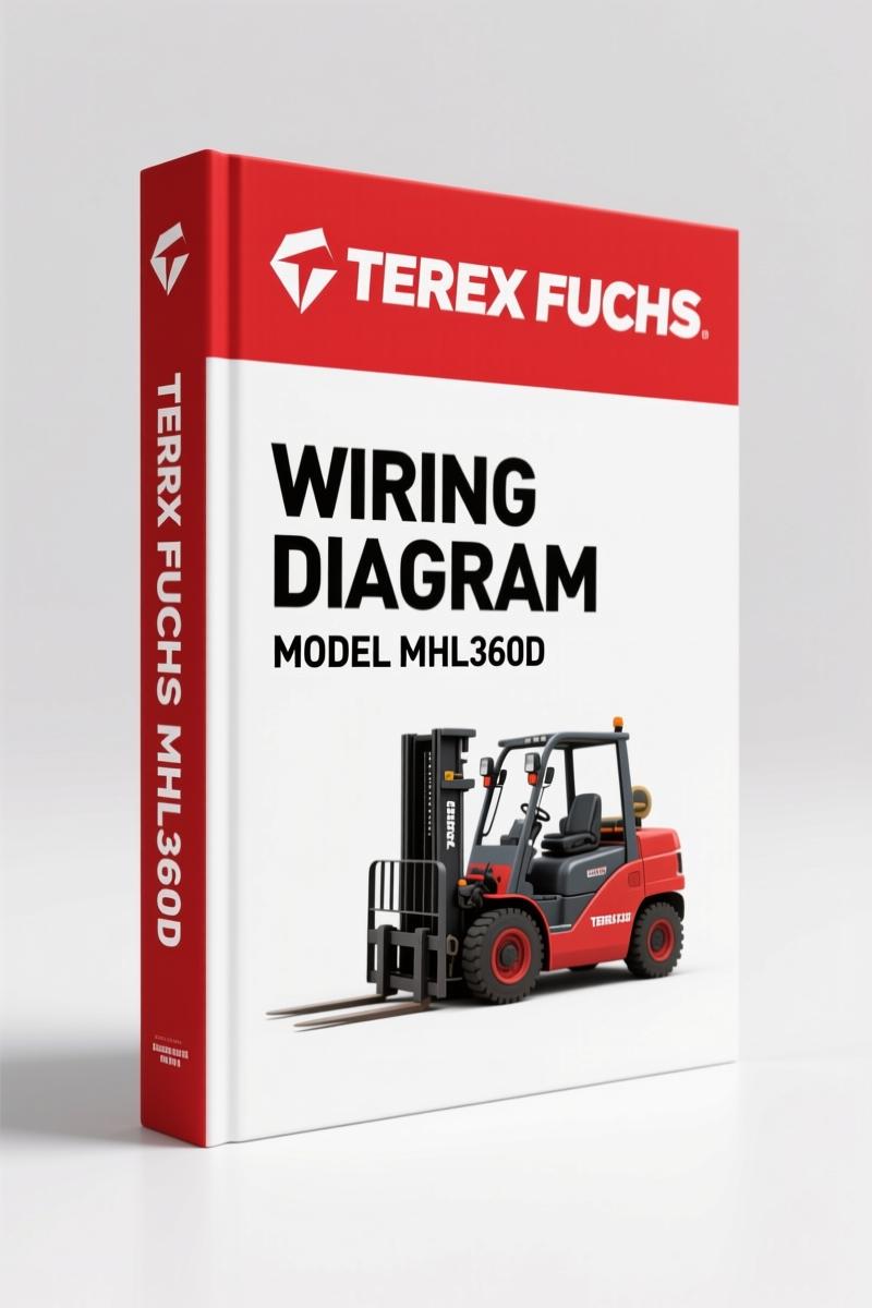
Terex Fuchs MHL360D Wiring Diagram – 127-Page OEM Electrical Schematic
Original price was: $62.40.$40.00Current price is: $40.00.
OEM Terex Fuchs MHL360D wiring diagram: 127 pages of factory electrical schematics for accurate diagnostics.
Description
Terex Fuchs MHL360D Wiring Diagram – Factory OEM Electrical Schematics
If you are staring at a pile of wires on your MHL360D and the machine won’t start, you need the factory wiring diagram. Not a third-party redraw. The original Terex Fuchs document – 127 pages of floor-plan accuracy. I’ve seen aftermarket diagrams that swap pin 13 and pin 8 on the joystick connector. That kind of mistake costs you a joystick board and a day of labor. This manual comes straight from the German engineering files. It uses the same component codes, the same grid coordinates, and the same DIN-standardized labeling that the factory techs use when they build the machine. Terex Fuchs MHL360D Wiring Diagram is what you need to trace any circuit from the battery isolation switch to the last LED on the cab floor.
Grenzlastregelung: What This Wiring Covers
The OCR snippet shows “Grenzlastregelung” – load limiting control. This is the circuit that prevents the machine from tipping or over-stressing the boom. The manual includes the Multifunktions-Eingabe-Knopf (MFB) interface, the joystick right and left assemblies, and the cab floor control board (Steuerung Kabinenboden). Each component is labeled with its exact grid location, like +020/13.A9 for the Steuerbox. You get the pin numbers, wire colors, and connector designations. No guesswork on which wire feeds the load-sensing valve.
127 Pages of Factory-Spec Circuits
127 pages, every single one a full-size schematic sheet. The manual covers the entire electrical system: engine start and glow plugs (Glühstifte Dieselmotor), battery isolation with G1 and G2, the central electrics box (Zentralelektrik B68), hydraulic oil cooler fan speed control (Lüfterdrehzahl Hydraulikölkühler), and the lighting circuits for both standard and Xenon headlights. Each sheet has a grid reference – A1 through H12 on most pages. You can take a voltage reading at pin 07/29.F5 and see exactly where that wire terminates on sheet 4.
Does This Manual Cover the Entire Chassis?
Yes. The diagram splits into two main sections: Oberwagen (upper structure) and Kabinenboden (cab floor). The upper structure includes the generator (G14), air differential pressure switch (S3), fuel filter water separator (RAA), and the grease pump system (Fettschmieranlage). The cab floor section covers the joystick harnesses, armrest switches, climate control (Klimaanlage B32), and the reversing camera. You also get the brake pressure monitoring circuit (Bremsdrucküberwachung) and the travel drive interlock. This is not a generic wiring booklet – it is the exact drawing set the factory uses for production.
Lighting and Signal Circuits: Standard vs. Xenon
The manual differentiates between standard headlights (H25, H26) and Xenon units (H25, H26 with Xenon suffix). Turn signals, parking lights, and horn are all mapped. The blinken links and blinken rechts (left/right turn signals) are on separate pages with their own fuses. If you have a dead left blinker, you can trace it back to connector +01/14.H2 without pulling the entire dash. The wiring also covers the work lights, cab interior lighting, and the warning beacon (Warneinrichtung Fahren).
Engine Start, Battery, and Safety Isolation
The battery system uses two batteries (G1 and G2) with a master disconnect switch (Batterietrennschalter S0). The manual includes the starting circuit (Anlasser Dieselmotor), glow plug relay (Vorheizrelais K2), and the idle speed control (Leerlaufautomatik). There is a dedicated page for the 30-terminal fuse distribution (Sicherungsverteiler Klemme 30). Critical safety note: the hydraulic pressure switch (S34C) for travel drive cutout is wired through the cab floor relay. If that relay fails, the machine won’t move. The diagram shows you exactly which relay – pin 02/17.C2.
I have used these factory wiring diagrams on three different MHL models. The difference between this OEM version and a reprint is the difference between a micrometer and a yardstick. The grid coordinates match the actual machine harness labels. You can verify continuity by reading the drawing, not by peeling back tape. For related models, check the TEREX FUCHS MHL380D Wiring Diagram and TEREX FUCHS MHL340D Wiring Diagram – same layout philosophy. Also see the Terex Fuchs MHL360 Electrical Schematic – Factory OEM Manual for a broader view of the entire electrical architecture.
If you need to understand automotive electrical fundamentals before diving into this diagram, the Automotive Wiring guide covers basic circuit theory. For advanced diagnostics, the Automotive Wiring resource offers troubleshooting methodologies that apply here.
FAQ – Terex Fuchs MHL360D Wiring Diagram
- Is this manual in English or German?
- The diagrams are in German (original factory language), but the schematic symbols, pin numbers, and grid references are universal. You do not need to read German to follow a wire from one connector to another.
- Does it include torque specs or fluid capacities?
- No. This is a wiring diagram only. No torque values, no fluid capacities. If you need the service manual for mechanical specs, look for the factory repair guide.
- Will this work on a MHL360 without the “D” suffix?
- The “D” denotes a specific generation with diesel engine and updated cab electronics. Earlier MHL360 models may have different pin assignments. Check your machine’s serial number against the manual’s applicability list.
- What if I find a wire color that doesn’t match the diagram?
- Factory wire colors can fade or be replaced during repair. Always verify by continuity test at the connectors. The diagram shows the intended factory routing – not field modifications.
You need wiring you can trust – not a scan of a scan. This is the original Terex Fuchs file, 127 pages, ready to print or view on any device. Access the Factory Manual now and get your MHL360D back to work.
Additional information
| Brand | Terex Fuchs |
|---|---|
| Language | English |
2 reviews for Terex Fuchs MHL360D Wiring Diagram – 127-Page OEM Electrical Schematic
You may also like…
-
Sale!
Terex Fuchs MHL380D Wiring Diagram – 144-Page OEM Electrical Schematic
Original price was: $85.80.$60.00Current price is: $60.00. -
Sale!
Terex Fuchs MHL340D Wiring Diagram – 73-Page OEM Electrical Schematic
Original price was: $54.00.$45.00Current price is: $45.00. -
Sale!
Terex Fuchs MHL340D 2008 Wiring Diagram – Factory Electrical Schematics
Original price was: $71.55.$45.00Current price is: $45.00. -
Sale!
Terex Fuchs MHL320D 2007 Technical Manual – OEM Assembly Drawings
Original price was: $61.65.$45.00Current price is: $45.00.
Related products
-
Sale!

Technical Manual – International 6.0L Power Stroke FICM Diagnostics
Original price was: $29.80.$20.00Current price is: $20.00. -
Sale!

1989 Service Manual – International 2000-8000 Electrical Systems
Original price was: $72.00.$50.00Current price is: $50.00. -
Sale!

2004 Acura TSX Wiring Diagram – 73-Page Factory Electrical Schematics
Original price was: $15.88.$9.99Current price is: $9.99. -
Sale!

2005 Parts Catalog – International NGD 3.0 L Engine (77 pages)
Original price was: $44.70.$30.00Current price is: $30.00.
William H. –
This is exactly what I needed. It is very easy to read on my phone without losing quality. It helped me to fix my Terex Fuchs Fuchs engine. I will definitely buy again.
Michael T. –
Excellent workshop guide. The document is very clear. It helped me to fix my Terex Fuchs Fuchs engine. Saved my repair job! Thank you.