
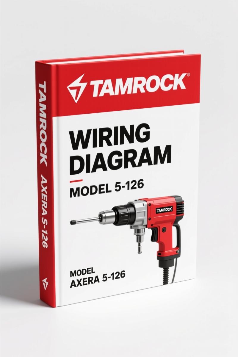
Tamrock AXERA 5-126 2006 Wiring Diagram – Factory Electrical Specs
Original price was: $100.10.$65.00Current price is: $65.00.
Factory wiring diagram for Tamrock AXERA 5-126 2006 drilling rig. 18 pages of OEM circuits, carrier wiring, diesel engine controls, and preventive maintenance data.
Description
Tamrock AXERA 5-126 2006 Wiring Diagram
If you’ve ever chased a short on a piece of heavy equipment using a third-party wiring diagram, you know the feeling of wanting to throw the whole machine into a river. I’ve been there. That’s why when I need a Tamrock AXERA 5-126 2006 Wiring Diagram, I go straight to the factory source. This 18-page document is the real thing – direct from Tamrock’s own Engineering Department. No translations, no guesswork, no diagrams that conveniently forget the emergency stop circuit. It’s the same schematic the dealer’s top technician pulls up on his tablet.
18 Pages of Factory Wiring – What’s Actually Inside
This isn’t some condensed cheat sheet. You get all 18 consecutive schematic sheets, starting with the contents and index list, then moving through main cabinets wiring, carrier wiring, diesel engine controls, carrier controls, supply and power pack starters, aux motor starters, 230VAC and 24VDC supply, working lights, emergency stop circuit, CPM1A input and output modules, S441 / WP and C control lights, contactor controls, oil temp and oil filter control, the 1-boom powerpack start/stop circuit, and the 1-boom return automatic sequence. Every sheet is numbered and revision-dated 2006-09-12. The page count alone tells you this is a serious piece of documentation – not a one-page sketch.
Diesel Engine Controls: Getting the Starting Circuit Right
The diesel engine controls sheet (section 4 of the diagram) is where most aftermarket copies fall apart. They’ll show you a generic starter motor circuit and call it good. This factory schematic traces every wire from the carrier battery (G1- and G2+) through the engine starter (M0) and includes the hot sensor on the compressor air circuit. If you’re swapping a starter or diagnosing a no-crank on the AXERA 5-126, you need the exact wire sizes and pin numbers Tamrock specified. Aftermarket diagrams will waste your time; this one won’t.
Emergency Stop Circuit: Why Aftermarket Diagrams Fail Here
Section 11 covers the emergency stop circuit. In a machine like the AXERA 5-126, a bypassed or miswired E‑stop can kill someone. The OEM diagram shows every contactor in the chain, including the interlocks feeding the working lights and the 24VDC supply. I’ve seen knockoff diagrams that simply draw a switch in series with the battery – that’s dangerous. This factory sheet gives you the actual logic, including the CPM1A output module interlock. Trusting a third-party copy here is gambling with your crew’s safety.
Audience: Who Needs This Diagram?
If you’re a workshop owner in San Antonio or a mobile tech who works on Tamrock drilling rigs, this is the difference between a four-hour fix and a full-day fire drill. The wiring diagram is aimed at mechanics who understand electrical schematics but need the correct terminal designations and component positions for the 380V/50Hz AXERA 5-126. Even if you’re a DIYer with good electrical chops, don’t touch the 1-boom powerpack starter without this document – it shows the exact thermistor and pressure switch wiring that prevents a burnt hydraulic pump. Professionals will appreciate the inclusion of the cable reel limit switches (S32, S33) and the water pump control (S428).
Source Validity: Tamrock OEM vs Aftermarket Copies
Every sheet in this PDF carries the Tamrock Oy copyright and notice stating it cannot be copied or reproduced without written consent. That’s a level of engineering ownership no reprint house can match. The ISBN or drawing number is 3-78114146-, and the ID‑code is 78114146. Compare that to an aftermarket product: they’ll strip the revision dates, remove the drawn-by name (PCH, checked by PCH, approved by AP), and call it a ‘reproduction’. This is a direct scan of the original Tamrock document. You get the header blocks, the revision table, the exact line weights. When you’re tracing a 4×2.5+C wire to a W28 junction box, you want the original – not a photocopy of a photocopy.
Related manuals you might need for the same fleet: Tamrock HE 122, HE 119, HE 300, HL 300, HL 300 S 2004 Operators Manual”>Tamrock HE 122, HE 119, HE 300, HL 300, HL 300 S 2004 Operators Manual covers the operator-level systems. If you’re going deeper into electrical diagnostics on other rigs, look at the Tamrock RANGER 700 RANGER 800 2003 Operators Manual | OEM”>Tamrock RANGER 700 RANGER 800 2003 Operators Manual | OEM and the Tamrock TF 500 TFX 500 2005 Repair Manual – OEM Specs”>Tamrock TF 500 TFX 500 2005 Repair Manual – OEM Specs. For general wiring knowledge that applies across brands, I keep an eye on Automotive Wiring”>Automotive Wiring fundamentals, but nothing replaces the factory drawing.
FAQ
- Does this cover the 380V/50Hz version or the 440V/60Hz version?
- The diagram is titled “AXERA 5-126 380V/50HZ”. The sheet 2 excerpt shows a 3‑ph supply labeled 440V 60Hz for certain components. If you have a 60Hz machine, you’ll still use this diagram – the wiring topology is identical, only the motor data plates differ. Verify your specific machine’s voltage before ordering parts.
- Are the wire sizes in metric or AWG?
- The diagram uses metric wire sizes (e.g., 4×2.5+C, 3×1.5). For North American conversions, 2.5 mm² is roughly 14 AWG and 1.5 mm² is about 16 AWG. Tamrock built these machines for global markets, so metric was standard. Use the cross-sectional area from the diagram, not a gauge chart, to match replacements.
- Can I use this to troubleshoot the 1-boom powerpack?
- Yes. Sections 17 and 18 cover the 1-boom powerpack start/stop and the 1-boom return automatic sequence. These include the thermistor (1R112), pressure switches (1S180, 1S190), and the solenoid (1Y47). If your boom wanders or refuses to start, this diagram shows every interlock.
- Why are there 18 sheets if the file is a single PDF?
- Each sheet corresponds to a physical page of the original engineering drawing set. The first sheet is the contents and index; sheets 2 through 18 are the actual wiring schematics. This isn’t a condensed handbook – it’s a proper set of fold-out drawings scanned one sheet per page. You get the full resolution of the original.
I’ve been turning wrenches for 28 years, and I can tell you the difference between a job that goes smoothly and one that eats your whole weekend is the quality of the documentation you start with. Grab the factory original while it’s still available. Access the Factory Manual now.
Additional information
| Brand | Tamrock |
|---|---|
| Language | English |
4 reviews for Tamrock AXERA 5-126 2006 Wiring Diagram – Factory Electrical Specs
You may also like…
-
Sale!

Tamrock TF 500, TFX 500 2005 Repair Manual – Factory Specs for Cylinder Feed
Original price was: $42.00.$30.00Current price is: $30.00. -
Sale!
Tamrock Axera 7, Axera 7 S 2006 Service Manual | Factory Maintenance Data
Original price was: $27.59.$19.99Current price is: $19.99. -
Sale!

Tamrock RANGER 700, RANGER 800 2003 Service Manual – Factory Specs
Original price was: $49.00.$35.00Current price is: $35.00. -
Sale!
Tamrock Axera 7, THC 560 2006 Service Manual – Factory Specs
Original price was: $88.80.$60.00Current price is: $60.00.
Related products
-
Sale!

1993 Operators Manual – International Bus 1000-3000 OEM Specs
Original price was: $12.30.$7.99Current price is: $7.99. -
Sale!
1996 Operators Manual – International 1000-4000 Series (246 pages)
Original price was: $15.28.$9.99Current price is: $9.99. -
Sale!
1995 Operators Manual – International 1000-4000 Series | OEM Documentation
Original price was: $12.49.$9.99Current price is: $9.99. -
Sale!
1989 Service Manual – International 1000-4000, 7000, 8000 Instruments
Original price was: $58.80.$40.00Current price is: $40.00.
Robert M. –
I am very pleased with this manual. Quick access after payment. Every torque spec is included for Tamrock AXERA. I will definitely buy again.
gearhead88 –
This is just what I needed. Quick access after checkout process. It assisted me to fix my Tamrock AXERA electrical system. Worth every penny.
pro_mechanic –
This is just what I was looking for. The scan is high-quality and easy to navigate. A must-have for any Tamrock AXERA owner doing maintenance. Saved my weekend project! Thanks.
Michael T. –
Perfect OEM spec sheet. The file is very clear. Contains clear schematics for Tamrock. I will recommend this shop to others.