
Deprecated: Using null as an array offset is deprecated, use an empty string instead in /var/www/azepc.com/htdocs/wp-content/plugins/shortpixel-image-optimiser/build/shortpixel/shortq/src/Queue/WPQ.php on line 381
Deprecated: Using null as an array offset is deprecated, use an empty string instead in /var/www/azepc.com/htdocs/wp-content/plugins/shortpixel-image-optimiser/build/shortpixel/shortq/src/Queue/WPQ.php on line 381
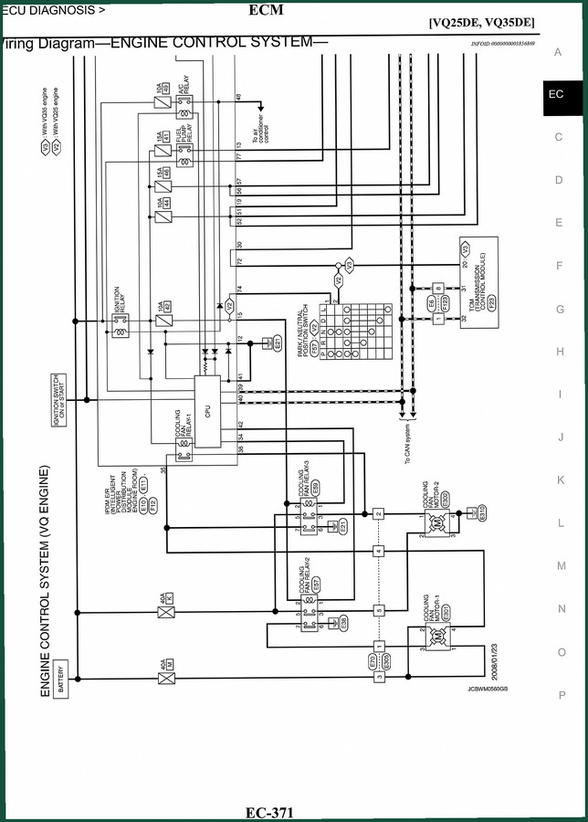
Nissan VQ35DE, VQ25DE Wiring Diagram – 16-Page Factory ECM Guide
Original price was: $25.92.$18.00Current price is: $18.00.
Factory 16-page wiring diagram for Nissan VQ35DE and VQ25DE engines. ECM diagnosis, sensor circuits, harness pinouts. OEM spec for professional use.
Description
Nissan VQ35DE, VQ25DE Wiring Diagram – Factory ECM Schematics
Ever chased a wire on a Nissan VQ engine using a generic aftermarket diagram and ended up with a shorted ECU? I’ve seen it. Guys spend half a day tracing a crank sensor signal only to find the aftermarket print had the pins swapped. This 16-page factory wiring diagram is the real deal – straight from Nissan’s engineering team. No reprints, no third-party redraws. You get the same schematics the dealer techs use. If you’re working on a Nissan VQ35DE, VQ25DE Wiring Diagram problem, this is the document you need on the bench.
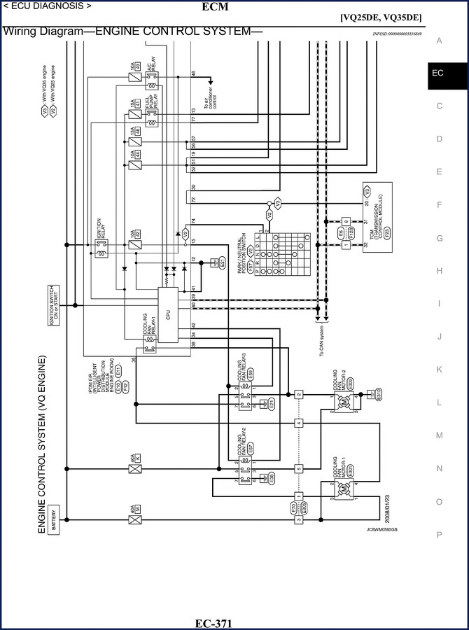
Wiring Diagram—Engine Control System—VQ25DE and VQ35DE
The manual opens with the ECM diagnosis section. Pagexa01 shows the full engine control system layout for both engines – ignition switch, relay, cooling fan motors 1 and 2, power steering system, CAN system. Every connector is labeled with factory codes like F114, F113, F116. You don’t guess which pin supplies power to the intake air temperature sensor; the diagram shows the circuit from the CPU straight to the sensor. The VQ25DE and VQ35DE versions are drawn side by side on the same page, so you can spot differences in harness routing immediately.
ECM Diagnosis: What This Manual Covers
Beyond the basic power and ground circuits, the diagram dives into the specific inputs and outputs the ECM expects. Pagexa02 covers the fuse block (JB), intake valve lift control relay, electronic throttle motor, data link connector (OBD), stop lamp switch, and the electronic power steering system control unit. Pagexa03 lists the crankshaft position sensors (UP and DN), engine speed sensor (NE), throttle position sensor, tensioner position sensing switches, engine balance shaft position sensor (VQ25DE only), brake fluid level sensor, back-up switch, brake air pressure sensor, exhaust gas temp sensors, and evaporative emission control valve. Every sensor has its own connector designation.
Does This Manual Include Sensor Locations?
Yes – and the harness layout notes. Pagexa03 has a warning that one connector is not shown in the harness layout, so you know exactly where to look. The diagram shows the ECM pins from 65 to 95 with specific sensor assignments. You get the injector circuit pressure sensor (fuel rail), manifold absolute pressure sensor, oil pressure sensors for both VQ25DE and VQ35DE, knock sensors bank 1 and 2, camshaft position sensors, heated oxygen sensors, engine coolant temperature sensor, battery sensor, and the fuel pump control relay. Pagexa05 adds the condenser fan motor relay, window switch, and injector circuits for both banks.
3 Critical Safety Warnings for Wiring Work
First: never probe a wire with a test light unless you know it’s a fused circuit. The ECM outputs delicate 5V reference signals; one short to ground and you’re buying a new ECU. Second: disconnect the battery before you start tracing continuity. The diagram shows multiple power feeds from the ignition switch and the fuse block – hot wires everywhere. Third: use the factory pin numbers, not the wire colors. Aftermarket diagrams often transpose colors; this OEM diagram uses connector and terminal designations, so you know pin F120 is the power steering combination switch supply. Trust the numbers, not the dye.
Why OEM Wiring Diagrams Beat Aftermarket Copies
I’ve had customers bring me aftermarket diagrams that combine several years into one mess. A 2005 VQ35DE diagram might show a different CAN bus layout than a 2008. This factory document is specific to the VQ25DE and VQ35DE engines as equipped in that generation. The page headers confirm “VQ25DE, VQ35DE” – no cross-model guesswork. The diagram even separates optional equipment like the intake valve lift control relay and the tensioner position switches. If you need to verify a pinout for the knock sensor on bank 2, it’s right there on pagexa04 with the exact ECM connector letter (H, I, J, K, etc.). No aftermarket repackaging can match that level of specificity.
Get the Right Pinout Data for Your Nissan
Whether you’re diagnosing a no-start, a misfire, or a parasitic draw, this 16-page wiring diagram gives you the factory paths. Pair it with the Nissan Engine Mechanical Service Training Manual for the mechanical side of the job, or grab the Nissan Murano 2002 User Manual if you need body electrical. For diesel guys, the Nissan Diesel TD27 Engine Parts Catalog 2006 has its own wiring. The principles of Automotive Wiring don’t change, but nothing beats the OEM sheet. Nissan’s Automotive Industry Overview won’t help you on the bench – this diagram will.
Frequently Asked Questions
- Is this diagram applicable to both VQ25DE and VQ35DE engines?
- Yes. The manual covers both engine variants in the same 16-page document. Each page explicitly labels sections for VQ25DE and VQ35DE where they differ.
- How does this wiring diagram compare to a generic aftermarket schematic?
- Aftermarket diagrams often merge multiple years, omit sensor references, and use generic pin labels. This OEM diagram shows factory connector codes (F110, F121, etc.), ECM pin numbers (65, 70, 75, 95), and specific sensor names like “Crankshaft Position Sensor (UP)” and “Camshaft Position Sensor 2 (Bank 2)”. It also notes when a connector is absent from the harness layout – a detail aftermarket copies routinely leave out. If you need to verify a 5V reference or a ground circuit, the OEM document eliminates guesswork and prevents misdiagnosis that can cost you a module.
Stop chasing phantom shorts with hand-drawn internet cartoons. Access the Factory Manual and get the same wiring data that Nissan service centers rely on.
Additional information
| Brand | Nissan |
|---|---|
| Language | English |
2 reviews for Nissan VQ35DE, VQ25DE Wiring Diagram – 16-Page Factory ECM Guide
You may also like…
-
Sale!

Nissan 280Z 1976 Service Manual – 681 Pages of Factory Specs
Original price was: $99.75.$75.00Current price is: $75.00. -
Sale!

Nissan 180SX 1991 Service Manual – 101 Pages, SR20DET Factory Specs
Original price was: $95.55.$65.00Current price is: $65.00. -
Sale!

Nissan 320 Service Manual – Factory OEM Specifications
Original price was: $103.35.$65.00Current price is: $65.00. -
Sale!

Nissan 200SX 1980 Service Manual – OEM Factory Specs
Original price was: $66.60.$45.00Current price is: $45.00.
Related products
-
Sale!

Service Manual – International HS 2.8L Engine – 130 Pages of Factory Specs
Original price was: $56.40.$40.00Current price is: $40.00. -
Sale!

2011 Parts Catalog – International 7400 SFA 6X6 – 1886 Pages of OEM Part Numbers
Original price was: $32.00.$25.00Current price is: $25.00. -
Sale!

International 1000-3000 Series Operators Manual – 132 Pages of OEM Specs
Original price was: $14.40.$10.99Current price is: $10.99. -
Sale!

2005 Parts Catalog – International NGD 3.0 L Engine (77 pages)
Original price was: $44.70.$30.00Current price is: $30.00.
Charles W. –
Perfect factory service manual. Quick access after payment. Contains precise bolt torque specs for Nissan. Saves me a lot of dollars.
James L. –
Five stars! The scan is high-quality and easy to navigate. A must-have for any Nissan VQ35DE, owner doing repairs. Highly recommended for mechanics.