
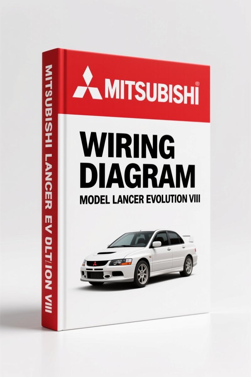
Mitsubishi Lancer Evolution VIII Wiring Diagram – 128 Pages Factory Specs
Original price was: $18.90.$14.00Current price is: $14.00.
128-page factory wiring diagram for Mitsubishi Lancer Evolution VIII. Covers 30+ electrical systems with wire color codes and junction block layouts.
Description
Mitsubishi Lancer Evolution VIII Wiring Diagram – Factory OEM Circuit Schematics
Look, I’ve lost count of how many times a generic wiring diagram sent a tech down the wrong wire. On a Mitsubishi Lancer Evolution VIII, you need the real thing—the factory Wiring Diagram, not some aftermarket guess. This manual is 128 pages of OEM circuit diagrams that cover every system from the Cooling fan to the Cylinder identification for ignition. No shortcuts. No reprints. Just the original Mitsubishi data.
128 Pages of Factory Wiring Data
The table of contents starts with HOW TO READ CIRCUIT DIAGRAMS and WIRE COLOR CODES—essential for anyone who’s stared at a tangle of wires. Then it moves through JUNCTION BLOCK, JOINT CONNECTOR, CENTRALIZED JUNCTION, and POWER DISTRIBUTION SYSTEM. Every major system gets its own section: STARTING SYSTEM, IGNITION SYSTEM, CHARGING SYSTEM, MFI SYSTEM, COOLING SYSTEM — that’s right, the cooling fan circuit is on page 90-42. You want to trace the cylinder head temp sensor? It’s in there. The manual also includes LINK_ID_REL_0: Mitsubishi Lancer Evolution Viii Simplified Wiring System if you want a consolidated view, but this is the full factory version.
Why Factory Wire Color Codes Matter
I’ve seen aftermarket manuals call a black-with-white-stripe a ground when it’s actually a switched 12V. On the Evolution VIII, that mistake can fry an ECU. The factory wiring diagram uses Japanese Industrial Standard color codes—exactly what the harness came with. Page 90-4 explains how to read them. Don’t trust a PDF that claims to have ‘equivalent’ colors. For background on why this matters, check out the LINK_ID_EXT_0: Automotive Wiring standards. Get the real thing.
Cooling System Circuit: What You Need to Check
When you’re troubleshooting a no-start on a Mitsubishi Lancer Evolution VIII, the first thing you do is check the ECM power and ground circuits. The starting system and ignition system diagrams in this manual show every relay, fuse, and connector. You can trace the starter signal from the ignition switch through the clutch interlock (if equipped) to the starter solenoid. One misread on an aftermarket diagram and you’ll be replacing parts that aren’t broken. I’ve seen guys throw a new crank sensor at it because a generic diagram showed the wrong pin. Don’t be that guy. The factory diagram lists the exact wire colors and connector views—C-126, C-127, etc. Use a multimeter and the manual, and you’ll find the break in 20 minutes. For SRS and ABS work, pair this with the LINK_ID_REL_1: Mitsubishi Lancer Evolution VIII Diagnostics Manual – Factory SRS Service Guide.
Get the Right Diagnostic Approach
Start with the multifunction fuse box (CENTRALIZED JUNCTION). Then check the fusible links. Do not skip the joint connectors—they are splice points that often corrode. The manual shows each joint connector location. For the stubborn electrical issues like the immobilizer or charge air cooler water spray system, the circuit diagrams are laid out in logical flow. You’ll also find ABS and SRS circuits—critical for safety. Never probe an SRS wire with a test light; use the manual’s pinout to back-probe properly.
Source Authenticity: OEM vs Aftermarket
This is a direct scan of the Mitsubishi factory publication. No aftermarket re-draw. The wire colors, connector shapes, and ground points are identical to what you’ll find under the dash. Compare that to a third-party manual that might combine multiple models. If you want to work on a different vehicle, check the LINK_ID_REL_2: Mitsubishi SPACE WAGON 1998 Wiring Diagram Factory Manual 165 Pages. For the Evolution VIII, stick with OEM. Factory data is the only way.
Stop wasting time. You need this manual on your workbench if you plan to diagnose any electrical issue on a Lancer Evolution VIII. From the starting system to the sunroof, the circuit diagrams are complete. Stop chasing ghosts with generic diagrams. Access the Factory Manual and get back to turning wrenches. For an overview of the industry, see LINK_ID_EXT_1: Automotive Industry Overview.
- Does this manual include the interior lights?
- Yes, dome light and luggage compartment light are covered.
- How do I find the correct wire color for the oxygen sensor?
- Look in the MFI SYSTEM section. The factory uses a specific color code for each sensor—front O2 is typically black/white and black/red, but don’t rely on memory. The manual lists every wire color in the circuit diagram. Also, the HOW TO READ CIRCUIT DIAGRAMS section explains the abbreviations (e.g., B = black, L = blue). Cross-reference with the actual harness because aftermarket replacement sensors sometimes have different wire colors—this manual gives you the factory pinout at the ECU connector. That’s the only way to be sure.
Additional information
| Brand | Mitsubishi |
|---|---|
| Language | English |
3 reviews for Mitsubishi Lancer Evolution VIII Wiring Diagram – 128 Pages Factory Specs
You may also like…
-
Sale!

Mitsubishi FB16N, FB18N, FB20CN Service Manual – 219 Pages of Factory Forklift Diagnostics
Original price was: $89.05.$65.00Current price is: $65.00. -
Sale!

Mitsubishi FB16KT, FB18KT, FB20KT Service Manual – 300-Page Factory Specs
Original price was: $86.45.$65.00Current price is: $65.00. -
Sale!

Mitsubishi FB16NT, FB18NT, FB20NT Service Manual – 272 Pages of OEM Forklift Specs
Original price was: $79.30.$65.00Current price is: $65.00.
Related products
-
Sale!

1992 Electrical Schematic – International 1000/3000/4000/2554 OEM Wiring Diagrams (132 Pages)
Original price was: $26.40.$20.00Current price is: $20.00. -
Sale!

Technical Manual – International 6.0L Power Stroke FICM Diagnostics
Original price was: $29.80.$20.00Current price is: $20.00. -
Sale!

1991 Operators Manual – International Truck OEM Specs (108 Pages)
Original price was: $13.63.$10.99Current price is: $10.99. -
Sale!

2005 Parts Catalog – International NGD 3.0 L Engine (77 pages)
Original price was: $44.70.$30.00Current price is: $30.00.
Richard G. –
Perfect factory service manual. It is very easy to read on my iPad without blur. Contains precise schematics for Mitsubishi. I will recommend this shop to others.
John S. –
Excellent factory service manual. It is easily zoomable on my laptop without blur. Contains detailed bolt torque specs for Mitsubishi. Saves me a lot of money.
Michael T. –
I am extremely satisfied with this manual. Instant access after checkout. A must-have for any Mitsubishi Lancer owner doing maintenance. Saves me so much time.