
Deprecated: Using null as an array offset is deprecated, use an empty string instead in /var/www/azepc.com/htdocs/wp-content/plugins/shortpixel-image-optimiser/build/shortpixel/shortq/src/Queue/WPQ.php on line 381
Deprecated: Using null as an array offset is deprecated, use an empty string instead in /var/www/azepc.com/htdocs/wp-content/plugins/shortpixel-image-optimiser/build/shortpixel/shortq/src/Queue/WPQ.php on line 381
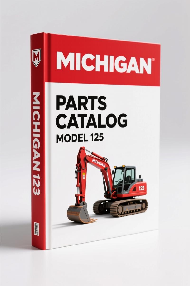
Michigan 125 Parts Catalog – OEM Exploded Views & Part Numbers
Original price was: $40.50.$30.00Current price is: $30.00.
240-page factory parts catalog for Michigan 125 including exploded views, wiring diagrams, and brake/cylinder assemblies. Genuine Clark part numbers.
Description
Michigan 125 Parts Catalog – Factory Parts Breakdown for CL. 32174-32189
You ordered what you thought was the right seal for the Michigan 125 and now the Parts Catalog you bought online gave you the wrong number. The new part doesn’t fit. Machine sits dead while you chase a refund. Every hour of downtime on a loader like the 125 costs real money. I have seen home mechanics and small shop owners waste a week flipping between three different parts websites trying to cross-reference a part that only fits a specific serial range. That is why this document exists.
This is the original factory Michigan 125 Parts Catalog, the one Clark Equipment printed in Belgium for model 125 III A machines carrying serial numbers CL. 32174 through CL. 32189. It runs 240 pages of exploded-view drawings, factory part numbers, and index references that tell you exactly which bolt, seal, or lever goes where. No third-party condensation. No photocopied blur. If you need a part for the bucket cylinder, brake assembly, or wiring harness on a GM-DAF variant 125, you need this book on the bench next to the coffee cup.
Engine & Mountings: Where the Manual Begins
Section 1 and 2 cover the engine and its mountings. If you have ever tried to order a vibration isolator from a generic parts site and got one that was two millimeters too tall, you know why page 1 matters. The engine oil pressure line routing sits on page 3. Fuel system breakdown runs pages 12 through 15. Radiator connections and mounting hardware? Pages 4 through 6. Every page shows the assembly exactly as it came from the factory, with the Clark part number printed next to each component.
Engine controls occupy pages 16-19, covering the linkage and levers that connect the throttle and shutoff to the pump. I have seen guys bend a control rod because they ordered a universal clevis pin instead of the correct shouldered pin from the diagram. That does not happen when you have the factory drawing sitting in front of you.
Battery, Carrier & Wiring: Electrical System Breakdown
The electrical section runs pages 47, 48, and 51 through 53 for the battery carrier and general wiring. Separate wiring diagrams exist for both the DAF powertrain (page 109) and the GM powertrain (page 61).
These are the actual factory schematics. They show wire colors, connector locations, and the routing through the frame. If you have an electrical gremlin in a loader that sits outside in San Antonio humidity, the first thing you check is the ground circuit in the battery carrier wiring. Page 47 shows the exact strap location and the bolt size for the frame ground. Aftermarket wiring diagrams usually merge multiple models into one drawing and leave out the factory ground path. This catalog does not do that. You can also check our related manual from the same series: Michigan Model 125 Series III Parts Manual. It covers a different serial range but uses the same layout.
A longer manual that shares the same structure: MICHIGAN 125 III A Parts Manual No 32156/165 which gives you additional pages of exploded views for the same machine family. Also check Volvo BM Michigan 125C 1988 Parts Catalog – Factory OEM Parts Manual if you are working on the later C-series machines.
Brake Assembly: Front and Rear – Factory Specs Only
Front brake assembly lives on pages 96-97. Rear brake assembly on pages 100-101. Brake controls and hydraulic lines in section 61. The wheel cylinder (page 50) and the parking brake lever (page 94) have their own exploded views.
Brake parts are the one place you cannot afford to guess. The wrong wheel cylinder bore diameter changes pedal feel and can lock a wheel prematurely. This catalog gives you the Clark part number for the front wheel cylinder and the rear wheel cylinder separately because they are not the same part. The foot brake controls section on page 95 shows the pedal linkage and the master cylinder mounting. If you have a soft pedal and air in the system is ruled out, check the brake de-clutch valve on pages 98-99. That valve interacts with the transmission control, and the factory diagram shows the port locations.
For context on why OEM documentation matters across the industry, you can read the Automotive Industry Overview on Wikipedia, which covers the standards behind these factory systems.
Cylinder Assemblies: Boom, Bucket, and Steering
Boom cylinder assembly appears on page 107. Bucket cylinder assembly on page 32. Steering cylinder assembly on page 34. Every cylinder in this catalog includes a full parts breakdown: piston, rod, seals, glands, and end cap retaining hardware. You can identify the exact seal kit without measuring anything. The boom cylinder on the 125 is a heavy piece of steel that lifts the front of the machine. If you rebuild it with the wrong gland nut thread pitch, you cross-thread the barrel. Page 107 shows the thread specification and the Clark part number for the gland nut. The bucket leveler lines are on page 49, and the bucket itself on page 109.
Steering cylinder assembly on page 34 is the same story. The steering system has its own hydraulic pump (page 31) and a separate front-end pump (page 30). The steering lines run pages 39-40. The steering gear goes on pages 44-45. If the wheel wanders, check the steering linkage on page 43 and the pressure relief valve on page 29. Do not adjust the relief valve without the factory setting printed in the manual. That setting prevents you from blowing seals in the steering gear.
3 Sections You Will Use Repeatedly
The drivetrain section includes the front differential and carrier assembly (pages 75-76), the rear differential and carrier assembly (pages 82-83), the transmission assembly and mountings (pages 57-59), and the torque converter assembly (pages 65-66). The clutch group (forward, reverse, and high) sits on pages 86-89. If you are pulling the transmission on a 125, those eight pages give you every shim, snap ring, and seal in order. The propeller shafts spread across pages 67-70. The mid-mount bearing assembly on pages 71-72 supports the center of the rear driveline.
Hydraulics come in two separate sections: front-end equipment hydraulics (pages 35-36) and transmission/torque converter hydraulics (pages 41-42). The reservoir hydraulic on pages 37-38 and the cockpit control valve on pages 27-28 round out the hydraulic coverage. If your bucket drifts down, check the bucket leveler valve on page 40 or 44. Both pages show the same valve from different angles.
Source Validity: One Original Print, Not a Reprint
This is a scan of the original OEM manual printed by Clark Equipment in Belgium. It says “MICHIGAN” on the cover, lists the serial number range CL. 32174-32189, and includes the index printed on heavy paper. The index alone tells you the machine is a 125 III A with a GM or DAF engine. You can verify the serial number range printed on page 1 against the data plate on your loader. Most aftermarket parts catalogs for this era of construction equipment copy the index but leave out the serial-specific part numbers that changed mid-production. This manual keeps every serial-specific part number. If you own a 125 that falls inside this serial range, every part number in this book is the one you order.
The different approaches to information in the Automotive Industry Overview show why OEM documentation is the standard reference for safe repairs.
FAQ
- Does this catalog cover the 125C or 125B models?
- This is for the Michigan 125 III A with serials CL. 32174-32189. The 125C and 125B use a different parts numbering system.
- What is the difference between this parts catalog and a service manual?
- A service manual tells you how to disassemble and reassemble components. A parts catalog gives you the factory part numbers and exploded views for ordering. You need both to rebuild a machine correctly, but this catalog is the one you use when the parts counter asks for the Clark number.
- Can I use this to replace the brake wheel cylinder without the service manual?
- If you have mechanical experience, the exploded view on page 50 shows the wheel cylinder assembly and part numbers. You still need the service manual for brake bleeding sequence and torque values on the backing plate bolts. The parts catalog gets you the correct cylinder.
- Are the wiring diagrams in color or black and white?
- The original print used black and white with dashed lines for different wire circuits. The DAF diagram on page 109 and the GM diagram on page 61 are both black and white factory schematics with wire color abbreviations printed in text.
This manual gives you the part number for every nut, seal, and hose on the 125. It stops the guesswork that costs a day of chasing wrong parts. Access the Factory Manual, print the pages you need, and keep the catalog on the toolbox when you order parts.
Additional information
| Brand | Michigan |
|---|---|
| Language | English |
4 reviews for Michigan 125 Parts Catalog – OEM Exploded Views & Part Numbers
You may also like…
-
Sale!
Michigan 175 III A Parts Catalog – 116 Pages OEM Exploded Views
Original price was: $3,930.00.$3,000.00Current price is: $3,000.00. -
Sale!

Michigan 55 III Parts Catalog – 122 Pages of OEM Exploded Views
Original price was: $96.00.$75.00Current price is: $75.00. -
Sale!
Michigan 65 AWS-R Parts Catalog – 214 Pages OEM Exploded Views
Original price was: $117.00.$75.00Current price is: $75.00. -
Sale!
Michigan 55A Parts Catalog – 94 Pages OEM Exploded Views
Original price was: $95.25.$75.00Current price is: $75.00.
Related products
-
Sale!

1993 Electrical Schematic – International 1000/3000/4000 Bus Chassis OEM Wiring Diagrams
Original price was: $29.26.$22.00Current price is: $22.00. -
Sale!

2011 Parts Catalog – International 7400 SFA 6X6 – 1886 Pages of OEM Part Numbers
Original price was: $32.00.$25.00Current price is: $25.00. -
Sale!

2004 Acura TSX Wiring Diagram – 73-Page Factory Electrical Schematics
Original price was: $15.88.$9.99Current price is: $9.99. -
Sale!
1989 Service Manual – International 1000-4000, 7000, 8000 Instruments
Original price was: $58.80.$40.00Current price is: $40.00.
pro_mechanic –
This is just what I required. Instant access after checkout. Contains detailed wiring diagrams for Michigan. I will recommend this shop to others.
John S. –
This is exactly what I required. Quick access after payment. It helped me to troubleshoot my Michigan 125 electrical system. Saves me a lot of dollars.
diy_master –
Superb resource! Immediate link after checkout process. Every torque spec is provided for Michigan 125. Great value for money.
William H. –
This is just what I required. The text is searchable and well indexed. It guided me to troubleshoot my Michigan 125 engine. Saved my repair job! Thanks.