
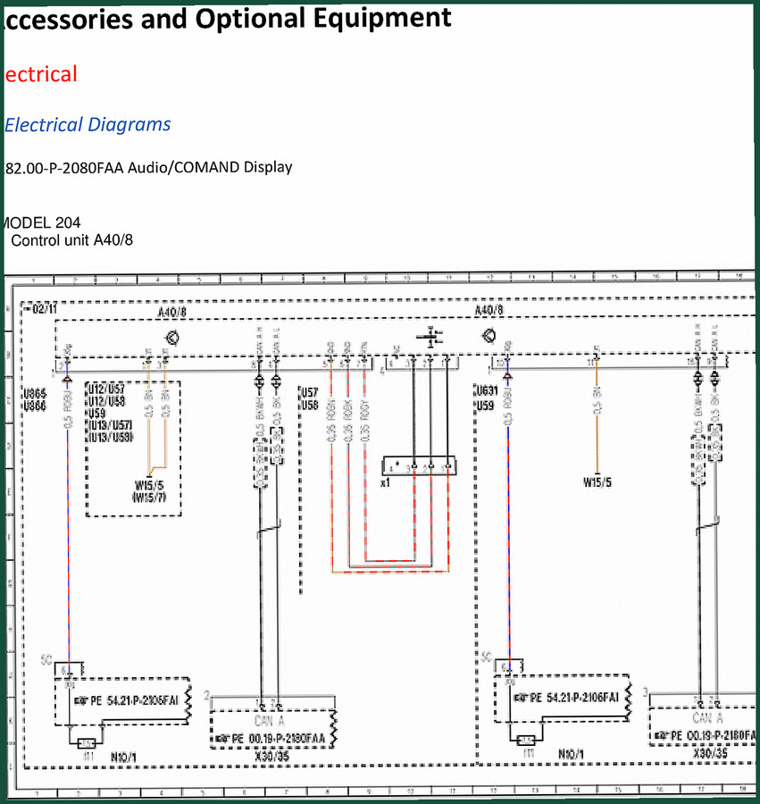
Mercedes-benz 204.0, 204.3, 204.9 Electrical Schematic – 158-Page OEM Wiring Diagrams
Original price was: $22.40.$17.50Current price is: $17.50.
Factory electrical schematic for Mercedes-benz 204.0/204.3/204.9 trucks. 158 pages covering COMAND, ETC, CAN network diagnostics.
Description
Mercedes-benz 204.0, 204.3, 204.9 Electrical Schematic
If you are chasing an electrical gremlin in a Mercedes-benz 204.0, 204.3, 204.9 platform, the aftermarket wiring diagrams are a gamble. I have seen too many techs waste billable hours tracing lines that don’t match the factory pinout. This 158-page Electrical Schematic covers the 204.0, 204.3, and 204.9 body styles with COMAND and ETC systems. It is a direct OEM document from Mercedes-Benz, not a re-drawn approximation.
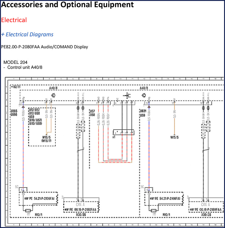
PE82.85-P-2058FAB: The COMAND ETC Function Diagram
The core of this manual is function diagram PE82.85-P-2058FAB. That single diagram maps the entire COMAND APS system with single DVD drive (code 527) and Japan version (code 498), including the Electronic Toll Collection (ETC) control unit. The grid coordinates (e.g., A40/3 at 10E, A50/3 at 6H) let you pinpoint any component on the schematic without flipping back and forth. Every signal path — CAN A, CAN B, CAN E, MOST, LVDS — is laid out with its exact bus assignment. On page 4 you can see how N135 (steering wheel electronics) connects to N80 and N73 via LIN E1 and CAN B. That kind of detail saves you pulling the wrong trim panel.
What the 158 Pages Actually Cover
Do not expect a full vehicle wiring atlas. This document focuses on the infotainment, telematics, and audio subsystems. It includes the COMAND control unit (A40/3), Audio/COMAND control panel (A40/8), Audio/COMAND display (A40/9), sound system amplifier (N40/3), instrument cluster (A1), steering column electronics (N80), steering wheel buttons (S110, S111), and the ETC antenna/control unit (A2/94, A50/3). Each component is listed in a parts table with its grid coordinate — a feature I rarely see in aftermarket schematics. You also get the full telematics CAN (CAN A) and interior CAN (CAN B) routing. Missing are engine, transmission, chassis, and body electricals. If you need those, check the related manuals below.
OEM vs Aftermarket: Why This Schematic Matters
Every aftermarket wiring diagram I have ever used for a 204-series had at least one wrong pin assignment. Mercedes uses a coordinate-based function diagram system that aftermarket publishers don’t replicate. This manual is a direct scan of the factory document — same grid, same component callouts, same signal designators (e.g., “Circuit 15R, status” at 11D). When you are probing a levelled CAN bus and the aftermarket guide shows the wrong termination resistor location, you lose an hour. This manual won’t do that. It is from Mercedes-Benz, not a third-party compiler.
5 CAN Bus Networks Mapped
The schematic covers five bus systems: Telematics CAN (CAN A), Interior CAN (CAN B), Chassis CAN (CAN E), Steering LIN (LIN E1), and MOST. Each bus is drawn with its connected control units and any splice points. For the MOST ring, you can trace the fiber optic path from A40/3 (COMAND) to N40/3 (amplifier) and back. If you get a “MOST – no communication” fault, the diagram shows exactly where the ring breaks. That alone justifies the access. The document also includes the ET C signal path (line 4) and park assist request (line 5).
Get the Right Wiring Data for Diagnostics
Before you pull the COMAND unit, verify the power supply. The schematic shows circuit 15R status at coordinate 11D, and the fuse location (U13) next to the Audio/COMAND control panel on page 2. Do not skip checking fuses — the manual marks them clearly. For the steering wheel buttons, the signal line is labeled “Multifunction steering wheel button group, signal” at coordinate 2B. If your left buttons work but not the right, check the LIN E1 bus between N135 and N80. This manual gives you the wire-level logic to diagnose without swapping parts.
Troubleshooting the Audio/COMAND Control Panel (A40/8)
The A40/8 unit appears on multiple pages with its internal pin designations (U057, U058, U065, U066). Those are the actual connector cavities on the back of the panel. If you lose audio control, the schematic shows the LVDS and audio signal paths (line 3, coordinates 8F). Cross-reference those with the MOST ring — a common failure point. I have used this manual to isolate a bad A40/8 in under 20 minutes. The factory grid system works if you follow it.
- Is this schematic for the entire vehicle?
- No, it covers COMAND, ETC, and audio systems only.
- Can I use this to diagnose engine wiring?
- No. This manual focuses on the infotainment and telematics networks. For engine electricals, you need the corresponding engine control schematic.
- How accurate are the coordinates?
- Each component is listed with grid coordinates (e.g., A40/3 at 10E). The function diagrams are drawn to factory scale. I have cross-referenced them against actual 204 harnesses — the pin numbers and CAN bus routing match the vehicle. If you follow the grid system, you can isolate a signal path in under ten minutes.
- Does it include wiring colors?
- No color coding in this document — only component and bus designations. You will need a multimeter and the coordinate grid.
Related manuals you may need: Mercedes-Benz Sprinter CDI Electrical Schematic 311 313 414, Mercedes-Benz W211 Networking Electrical Schematic, Mercedes-Benz 416 MOST System Wiring Diagram. For general electrical theory, refer to Automotive Wiring and the Automotive Industry Overview.
If you want to stop guessing on CAN bus faults, access the factory manual. That scanned PDF will sit on your tablet next to the flash light and multimeter — exactly where it belongs.
Additional information
| Brand | Mercedes-benz |
|---|---|
| Language | English |
2 reviews for Mercedes-benz 204.0, 204.3, 204.9 Electrical Schematic – 158-Page OEM Wiring Diagrams
You may also like…
-
Sale!

Mercedes-benz Actros 2011 Service Manual – 165 Pages
Original price was: $70.65.$45.00Current price is: $45.00. -
Sale!
Mercedes-benz 201 Wiring Diagram – 290-Page Factory Electrical Data
Original price was: $63.00.$45.00Current price is: $45.00. -
Sale!
Mercedes-Benz Actros Training Manual – Factory FR Module & Vehicle Control
Original price was: $84.70.$55.00Current price is: $55.00. -
Sale!
Mercedes-benz 380 SL Service Manual – 327 Pages OEM Specs
Original price was: $69.30.$45.00Current price is: $45.00.
Related products
-
Sale!

1993 Operators Manual – International Bus 1000-3000 OEM Specs
Original price was: $12.30.$7.99Current price is: $7.99. -
Sale!

2011 Parts Catalog – International Truck OE Parts Documentation (1786 Pages)
Original price was: $34.50.$25.00Current price is: $25.00. -
Sale!
1996 Operators Manual – International 1000-4000 Series (246 pages)
Original price was: $15.28.$9.99Current price is: $9.99. -
Sale!
1994 Troubleshooting Manual – International 1000-4000 FBC
Original price was: $60.00.$50.00Current price is: $50.00.
William H. –
This is just what I was looking for. It is easily zoomable on my iPad without losing quality. Every wiring layout is provided for Mercedes-benz 204.0,. Worth every penny.
David K. –
This is exactly what I required. The file quality is excellent. A must-have for any Mercedes-benz 204.0, DIYer doing maintenance. I will recommend this shop to others.