
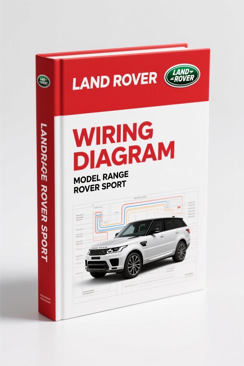
Land Rover Range Rover Sport Wiring Diagram – 318 Pages of Factory Electrical Data
Original price was: $37.80.$30.00Current price is: $30.00.
OEM wiring diagram for Range Rover Sport, 318 pages. Covers suspension, engine controls, adaptive systems, and connector pinouts.
Description
Land Rover Range Rover Sport Wiring Diagram – What You Get with 318 Pages
If you have spent an afternoon tracing a short in a Land Rover Range Rover Sport with nothing but a multimeter and a generic wiring booklet, you already understand why that approach costs you billable hours. The factory Wiring Diagram for this vehicle is 318 pages of Land Rover’s own circuit layouts, connector views, and ground distribution paths. I have torqued enough head bolts to know that guessing a connector pinout leads to fried modules. This manual removes that guesswork. It covers VIN range 300000 and beyond, LHD, with every subsystem from the deployable towbar to the 23-speaker audio system. The publication part number is JLJR 18 53 21_2E, printed by Jaguar Land Rover Limited. You get the same document their dealership techs use.
7 Systems Covered – From Suspension to CAN Bus
Look at the table of contents. Section 204-05 covers Suspension – Vehicle Dynamic Suspension wiring. That is not a generic air-ride schematic. It shows the exact wire colors, pin numbers, and module locations for the Range Rover Sport’s adaptive damping system. Section 204-06 gets into Ride and Handling Optimization – Dynamic Response and Terrain Response. If you have ever had a Terrain Response fault that killed the suspension compressor, you know the value of having the factory circuit diagram for the solenoid valves. The manual also dedicates three full sections (303-14A through 303-14E) to Electronic Engine Controls for DV6, PV6, DV8, and PV8 (5.0L). That means fuel injector wiring, crank sensor paths, and ECM pinouts – not a third-party interpretation.
Adaptive Speed Control and Module Communications
Section 310-03 covers Speed Control – Adaptive. That is the radar-based cruise system. The wiring for that system runs through the high-speed CAN bus, which is detailed in Section 418-00. You will find separate diagrams for Medium speed CAN, High speed CAN, MOST (conventional and virtual display), LIN bus, and LVDS connectivity. When a customer complains that the adaptive cruise stopped working after a stereo install, you need to know which wire in the gateway module got back-fed. This manual shows the entire network topology. Page numbers are not scattered – each subsystem starts on its own page. The abbreviation list at the front (page ix) decodes every acronym used in the schematics.
Terrain Response and Wade Sensing: Factory-Specific Sections
Section 204-06 includes Wade Sensing System wiring. If you have never seen the Wade Sensing circuit – the sensors that measure water depth – you might waste time chasing a non-existent ground fault. The manual shows the sensor power, ground, and signal wires with the exact pin numbers at the module. Also in that section: Dynamic Response sway-bar disconnect wiring. That system uses a pump and solenoid pack that draws high current. The wiring diagram includes fuse ratings and relay positions. Aftermarket manuals often skip these specialized circuits because they assume you will never need them. Land Rover does not assume that.
Source Authenticity: Factory OEM vs Aftermarket Copies
I have seen aftermarket wiring manuals that list “typical” wire colors – blue/white may actually be brown/purple on a Range Rover. This manual is the factory publication. It is scanned from the original Land Rover electronic source. Every connector view is a Land Rover drawing, not a re-drawn approximation. The health and safety instructions at the start (page xi) are the same ones Land Rover provides to dealer techs. Aftermarket manuals rarely include safety warnings for high-voltage circuits like the fuel fired booster heater or the block-heater. This one does. If you work on these vehicles regularly, you know that a wrong wire splice can set off the CAN bus or trigger the passive start anti-theft system. The factory wiring diagram is your only reliable reference.
Does This Manual Cover the PV8 5.0L Engine and the Hybrid Systems?
Section 303-14E is specifically for Electronic Engine Controls – PV8 (5.0L). Yes, it covers the supercharged 5.0L. The starting system section (303-06) includes separate diagrams for DV6 with Stop-Start and DV8. There is no hybrid-specific section listed in this edition – this document predates PHEV models. For those, you need a later publication. But for the 2013-era Range Rover Sport (LHD), every engine variant is covered down to the cooling fans (303-03) and the automatic transmission (307-01).
What Tools and Safety Gear Should You Have Before Opening This?
A decent multimeter with a good probe set. A scan tool that can read CAN bus messages. A set of trim clip removers for the interior panels. And a fire extinguisher – because working on a vehicle’s electrical system with the battery connected is a risk. This manual will tell you which circuits remain live after the ignition is off (quiescent current control module, Section 414-01). Do not assume the battery junction box is dead. The manual includes ground distribution diagrams for all junction boxes (engine, battery, central, rear). Print the relevant pages and keep them clean – grease on paper does not help.
Related Manuals for Your Range Rover Sport
- Land Rover Range Rover Sport Wiring Diagrams – Full set of electrical schematics for all years.
- Land Rover Range Rover Sport Electrical Wiring Diagram – Section: 413-06 – – Horn and auxiliary circuits detailed.
- Land Rover Range Rover Sport Electrical Wiring Diagrams – Alternative format for quick reference.
If you need a broader understanding of vehicle electrical theory, read up on Automotive Wiring basics. For deep dives into CAN bus diagnostics, see Automotive Wiring video tutorials.
FAQ: Two Questions About This Manual
- Does the manual include wiring for the heated windshield and washer jets?
- Yes. That is Section 412-02 – Auxiliary Climate Control. You get the heated windshield, heated rear window, heated washer jets, fuel fired booster heater, and block-heater circuits. The schematics show the relay positions and fuse allocation for the heated windshield grid. Aftermarket manuals often lump all heaters into one generic diagram. This manual separates them by system.
- What about the battery junction box variations?
- Section 414-01 covers every option: DV6, DV6 cold climate, DV8 cold climate, and Petrol. Each diagram shows the exact fuse layout.
Access the Factory Manual – the 318-page Land Rover Range Rover Sport wiring diagram – and keep it on your tablet or printed binder. Your future self, staring at a dead module, will thank you.
Additional information
| Brand | Land Rover |
|---|---|
| Language | English |
2 reviews for Land Rover Range Rover Sport Wiring Diagram – 318 Pages of Factory Electrical Data
You may also like…
-
Sale!
Land Rover Defender Workshop Manual – 1213 Pages of Factory Specs
Original price was: $62.80.$40.00Current price is: $40.00. -
Sale!
Land Rover Defender 2007 Electrical Schematic – 338-Page OEM Circuit Data
Original price was: $53.20.$40.00Current price is: $40.00. -
Sale!
Land Rover Defender 1996 Workshop Manual – Factory Specs for 300Tdi
Original price was: $63.20.$40.00Current price is: $40.00. -
Sale!
Land Rover Freelander 2003 Wiring Diagram – Factory Electrical Schematics
Original price was: $58.95.$45.00Current price is: $45.00.
Related products
-
Sale!

1991 Operators Manual – International Truck OEM Specs (108 Pages)
Original price was: $13.63.$10.99Current price is: $10.99. -
Sale!

2011 Parts Catalog – International Truck OE Parts Documentation (1786 Pages)
Original price was: $34.50.$25.00Current price is: $25.00. -
Sale!

2004 Acura TSX Wiring Diagram – 73-Page Factory Electrical Schematics
Original price was: $15.88.$9.99Current price is: $9.99. -
Sale!

1993 Operators Manual – International Bus 1000-3000 OEM Specs
Original price was: $12.30.$7.99Current price is: $7.99.
gearhead88 –
I am very pleased with this transaction. It is very easy to read on my tablet without blur. Every wiring layout is included for Land Rover Rover. I will recommend this shop to others.
David K. –
I am very pleased with this purchase. It is easily zoomable on my phone without blur. Every torque spec is provided for Land Rover Rover. I will definitely buy again.