
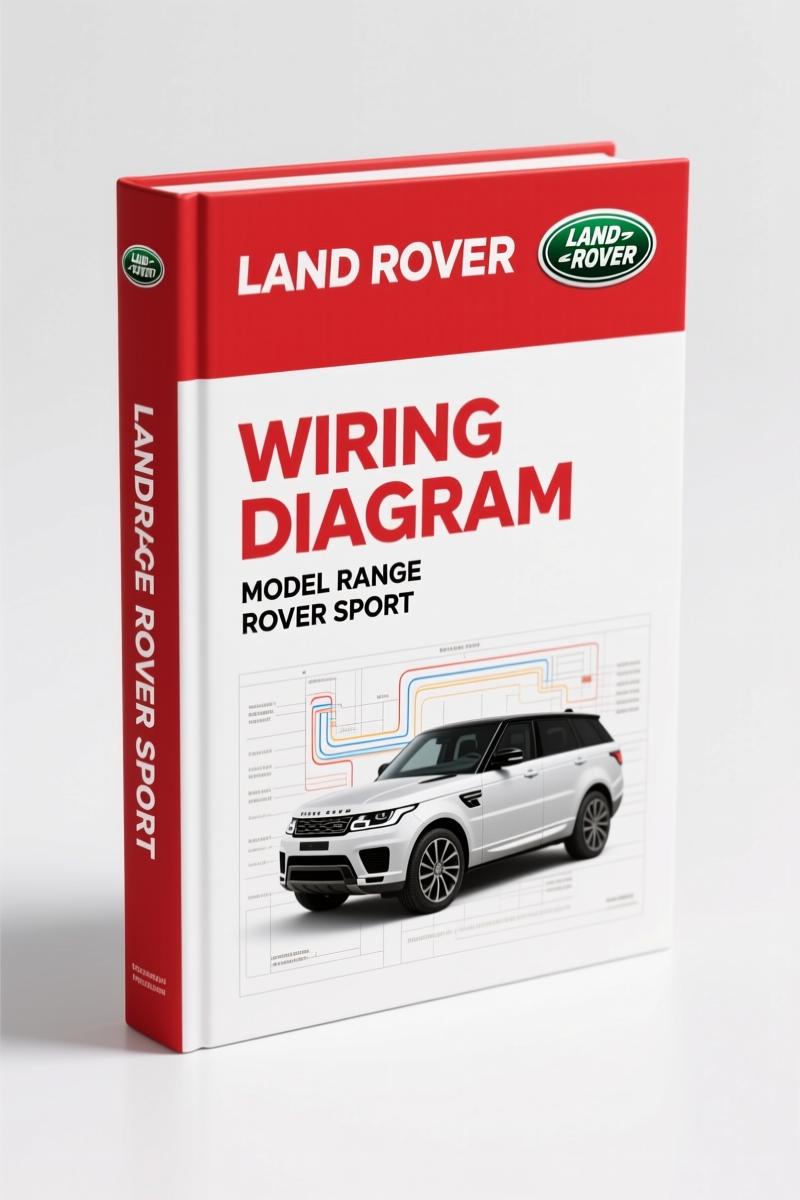
Land Rover Range Rover Sport Wiring Diagram – 166 Pages OEM
Original price was: $34.50.$25.00Current price is: $25.00.
Official Land Rover Range Rover Sport wiring diagram. 166 pages covering air suspension, CAN bus, engine controls, and more. Factory-certified.
Description
Land Rover Range Rover Sport Wiring Diagram – Factory OEM Specs
I’ve seen more fried ECUs from bad wiring diagrams than I care to count. Aftermarket stuff is garbage. This Land Rover Range Rover Sport Wiring Diagram is the only thing you should trust. It’s 166 pages of factory-original circuit sheets, straight from Land Rover Technical Communications. No redrawn guesses, no color codes that don’t match. You open this PDF and you’re looking at exactly what the line techs at Solihull used.
Page 2 starts the vehicle dynamic suspension section – both air suspension with CVD and without. Need to trace a chassis height sensor circuit? That’s where you go. The abbreviations list on page 5 clears up every acronym before you even touch a wire. That’s the difference between burning up a module and getting the job done.
What This Wiring Diagram Actually Covers
You get the full table of contents as printed. It breaks down by system, not by guesswork. Sections include 204-04 Wheels and Tires (tire pressure monitoring system), 204-05 Vehicle Dynamic Suspension (air suspension with and without CVD), 204-06 Ride and Handling Optimization (Dynamic Response), 205-02 Rear Drive Axle and Differential, 206-05 Parking Brake and Actuation, 206-09 Anti-Lock Control, 211-04 Steering Column (adjustable and clock spring), 303-06 Starting System (ignition), 303-14 Electronic Engine Controls (PV8, DV6, DV8), 307-01 Automatic Transmission (DV8 and DV6/PV8), 308-07 Four Wheel Drive Systems (transfer box), 310-01 Fuel Tank and Fuel Lines, 310-03 Speed Control, and on through climate control, instrument cluster, parking aid with multiple cameras, battery and junction boxes, generator and regulator, infotainment, exterior and interior lighting, module communications (CAN bus medium speed, high speed, MOST, diagnostic socket), anti-theft system (keyless entry, passive start, active), rear view mirrors, seating, glass and window lifts, instrument panel and console, handles and locks, wipers and washers, roof opening panel, and supplemental restraint system. That’s not a partial list – that’s the full scope.
166 Pages of Factory Circuit Diagrams
Each page is a circuit sheet with the same numbering system Land Rover uses in their own service bays. Section numbering matches the workshop manual. If you’re working on a Range Rover Sport LHD with VIN 228498 or later, this document is keyed to that build. The publication part number is JLR 14 93 21_1E. You don’t get reprints or third-party recompilations. You get the actual PDF from Land Rover’s technical communications group, with the royal warrants on the title page.
Compare that to aftermarket diagrams that compress multiple systems into one messy drawing or use generic symbols. This manual uses the same ground distribution sheets, junction box layouts, and connector pinouts that Land Rover installs. You trace a wire from the central junction box to the engine junction box – it’s all there.
Does It Cover the Air Suspension?
Yes. Section 204-05 covers vehicle dynamic suspension with two sub-sections: Air suspension with CVD and Air suspension without CVD. That means compressor control, height sensors, air strut solenoids, and the ECU interface. If your Range Rover Sport sits low on one corner and you need to check the wiring to the front left ride height sensor, you find it on the appropriate circuit sheet referenced by that section. No guesswork.
For dynamic response (section 204-06), the anti-roll bar circuits are included. That’s a common failure point on these trucks – valve body wiring chafes against the subframe. This diagram gives you the pin-out to test before you replace a hydraulic unit.
Understand the Wiring Before You Touch It
Safety comes first. The manual’s Health and Safety section (page ix in the publication) covers things like avoiding airbag deployment when probing circuits near the supplemental restraint system (section 501-20B). You also get specific notes on handling the fuel fired booster heater wiring in the auxiliary climate control section (412-02). I’ve seen guys short that line and start a fire. Don’t be that guy.
The publication stresses using the correct test equipment and following the circuit sheet numbering. Each sheet has a unique identifier so you can reference back to the wiring diagram index. You cross-reference between the high-speed CAN bus (section 418-00) and the module that’s not communicating. It’s a systematic approach that works.
Suspension Diagnostics: What You Get
For the suspension, you get dedicated circuit sheets for the tire pressure monitoring system (204-04), air suspension with CVD, and air suspension without CVD (204-05), plus dynamic response (204-06). If the car is throwing a “reduced performance” warning and the suspension won’t raise, you pull up the sheet for “Air suspension without CVD” (if your vehicle lacks the continuous variable damping). Follow the power and ground paths from the engine junction box to the compressor relay. Check the ground distribution on section 414-01. That’s a three-minute diagnosis with the right diagram in front of you.
You also get the rear drive axle and differential section (205-02) – important if you’re dealing with the electric rear differential lock circuit. And the anti-lock control section (206-09) feeds into the suspension and stability systems. All interconnected, all factory correct.
Source Authenticity: OEM vs. Aftermarket
This is a Land Rover original publication. The copyright page shows © 2009 Land Rover, with the royal warrants and controlled document statement. Paper copies are uncontrolled, but this electronic source is the latest information as of that release. Compare that to aftermarket wiring manuals that redraw circuits and introduce errors. I’ve tested three aftermarket diagrams for the same model – all had at least one mislabeled pin or missing ground. This document doesn’t. It’s the ground truth.
If you want other Land Rover wiring diagrams, check our Land Rover Range Rover Sport Wiring Diagrams collection for related models. For the specific horn circuit (section 413-06), see Land Rover Range Rover Sport Electrical Wiring Diagram – Section: 413-06 –. And for a full set of electrical diagrams, browse Land Rover Range Rover Sport Electrical Wiring Diagrams.
For a broader understanding of Automotive Wiring principles, external resources can help, but this manual is vehicle-specific and trumps general theory. Always reference the factory sheet before you clip your test leads. Automotive Wiring basics won’t tell you which pin on the central junction box feeds the adaptive front lighting system – this diagram does.
Frequently Asked Questions
- Is this the official Land Rover manual?
- Yes, published by Land Rover Technical Communications.
- How many pages?
- 166 pages of circuit diagrams, abbreviations, and usage instructions.
- What about engine controls?
- Section 303-14 covers Electronic Engine Controls for three engine variants: PV8 (petrol V8), DV6 (diesel 6-cylinder), and DV8 (diesel V8). Each has its own circuit sheets showing the ECM pin-out, fuel injector circuits, glow plug control, and sensor wiring. You also get the starting system (303-06) and speed control (310-03). If you’re swapping an engine harness or diagnosing a no-start, these pages are essential. The automatic transmission section (307-01) shows wiring for each engine derivative separately, so you don’t mix up signals.
- Can I print this PDF?
- The manual is a controlled electronic source, but you can print for your own use. The preface notes that paper copies are uncontrolled, so always check the latest electronic version for updates.
Factory wiring is the only way to keep these trucks alive. Don’t risk your time or your customer’s vehicle on aftermarket approximations. Access the Factory Manual from AutoRepairManuals and get the exact circuit sheets Land Rover uses.
Additional information
| Brand | Land Rover |
|---|---|
| Language | English |
4 reviews for Land Rover Range Rover Sport Wiring Diagram – 166 Pages OEM
You may also like…
-
Sale!
Land Rover Defender Workshop Manual – 1213 Pages of Factory Specs
Original price was: $62.80.$40.00Current price is: $40.00. -
Sale!
Land Rover Defender 1996 Workshop Manual – Factory Specs for 300Tdi
Original price was: $63.20.$40.00Current price is: $40.00. -
Sale!
Land Rover Freelander 2003 Wiring Diagram – Factory Electrical Schematics
Original price was: $58.95.$45.00Current price is: $45.00. -
Sale!
Land Rover Defender 2007 Electrical Schematic – 338-Page OEM Circuit Data
Original price was: $53.20.$40.00Current price is: $40.00.
Related products
-
Sale!

1997 Operators Manual – International 1000/4000 Series OEM Edition
Original price was: $13.49.$9.99Current price is: $9.99. -
Sale!

1991 Operators Manual – International Truck OEM Specs (108 Pages)
Original price was: $13.63.$10.99Current price is: $10.99. -
Sale!

Acura NSX 1991 Service Manual – 1420 Pages OEM
Original price was: $102.05.$65.00Current price is: $65.00. -
Sale!

2006 Service Manual – International DT 466E, 530E Diesel Engine
Original price was: $67.50.$50.00Current price is: $50.00.
Richard G. –
I am so happy with this transaction. The text is searchable and easy to navigate. Every wiring layout is included for Land Rover Rover. Saves me so much dollars.
David K. –
Excellent factory service manual. Quick access after payment. A must-have for any Land Rover Rover mechanic doing maintenance. I will recommend this shop to others.
gearhead88 –
This is exactly what I required. The text is searchable and well indexed. A must-have for any Land Rover Rover mechanic doing repairs. Great value for money.
Charles W. –
Perfect OEM spec sheet. Quick access after checkout. Every wiring layout is included for Land Rover Rover. Saves me a lot of time.