
Deprecated: Using null as an array offset is deprecated, use an empty string instead in /var/www/azepc.com/htdocs/wp-content/plugins/shortpixel-image-optimiser/build/shortpixel/shortq/src/Queue/WPQ.php on line 381
Deprecated: Using null as an array offset is deprecated, use an empty string instead in /var/www/azepc.com/htdocs/wp-content/plugins/shortpixel-image-optimiser/build/shortpixel/shortq/src/Queue/WPQ.php on line 381
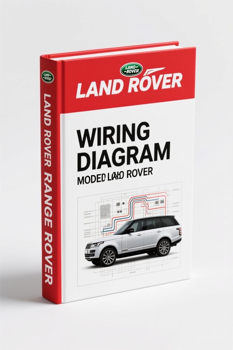
Land Rover Range Rover 2001 Electrical Schematic – 223 Pages
Original price was: $27.60.$20.00Current price is: $20.00.
OEM electrical schematic for 2001 Range Rover. 223 pages covering all circuits: Td6/V8, ABS, SRS, CAN bus, fuse boxes, earth points.
Description
Land Rover Range Rover 2001 Electrical Schematic – Factory Electrical Circuit Diagrams
If you’ve ever tried tracing a short on a 2001 Range Rover using some aftermarket wiring diagram you found online, you know the pain. Colors don’t match. Splices are missing. Ground points are wrong. That’s why this Land Rover Range Rover 2001 Electrical Schematic is what you need on your bench. 223 pages of factory color codes, circuit diagrams, and pinouts printed by Land Rover themselves. Not a reprint. Not a scan from a third-party. This is the OEM publication part number LRL 0499ENG. I’ve been turning wrenches for 28 years, and I will tell you straight: if you don’t have the factory diagram, you’re guessing. And guessing on a Range Rover electrical system means replacing control units you didn’t need to replace.
What’s Inside the 223 Pages?
The manual is organized by system – exactly how Land Rover’s engineers laid it out. You get power distribution starting at page 8 with the engine compartment fuse box and the passenger compartment fuse box. Then earth distribution on page 18 – that section alone has saved me hours of chasing bad grounds. The table of contents covers every system: anti‑theft alarm, engine immobilisation (Td6 and V8), central door locking, windows, sunroof, door mirrors with memory and folding circuits, seats (front, memory, lumbar, heated), steering wheel adjustments, charging and starting, engine management for both Td6 and V8, fuel pump, secondary air injection, cooling fans, cruise control, electronic automatic transmissions (GM5 and ZF), air suspension, ABS, SRS, air conditioning (low‑line and high‑line), fuel burning heater, heated screens, wipers and washers, exterior and interior lamps, instruments, audio systems, navigation, television, tyre pressure monitoring, park distance control, and trailer socket. Every circuit includes the factory color codes from page 3 – the color code table lists 14 colors with their letter codes. No guessing what “U” means – it’s blue.
Does This Manual Cover the Engine Management System?
Yes – and it does it properly. The engine management section is split by engine: Td6 diesel and V8 petrol. Each has multiple pages showing the ECM, sensors, injectors, ignition coils, and all wiring paths. You’ll find the pin assignments for the connectors and the exact wire colors that match the harness. I’ve used the V8 diagrams to diagnose a misfire caused by a chafed wire on the secondary air injection circuit – the diagram showed me the splice location I would never have found with a generic schematic. The manual also includes the engine immobilisation diagrams – that’s critical when you’re dealing with a no‑start that turns the engine over but won’t fire. The immobiliser module communicates with the BCU over the K‑bus, and the manual shows exactly which wires carry that signal.
Earth Distribution: A Common Diagnostic Trap
Page 18 is the earth distribution page. If you skip it, you’ll chase electrical ghosts. I’ve seen people replace alternators, batteries, and even ECMs because of a corroded ground at G201. This manual shows every earth point by location and wire gauge. The Range Rover uses multiple grounding studs in the engine bay, passenger compartment, and rear. The earth distribution diagram maps them all. When you have a random electrical fault that affects multiple systems, start here. Check the Automotive Industry Overview for common ground failure patterns, but the manual is your primary tool.
3 Reasons to Use OEM Documentation Over Aftermarket
First, the color codes are verified against Land Rover’s own harness production. Aftermarket diagrams often swap colors or use generic labels – on a Range Rover that will lead you to the wrong wire every time. Second, splice locations are factory‑mapped. The manual includes sections for splices and centre taps – those hidden junctions that aftermarket diagrams ignore. Third, this electrical schematic incorporates the updates from Land Rover’s service bulletins through 2001. You get the production‑correct version, not a generic approximation. Land Rover Range Rover Electrical Wiring Diagrams – Section: Pv8 covers the V8 engine management specifically if you need more detail on that one engine.
Get the Right Fuse Box Diagram
The manual devotes multiple pages to the engine compartment fuse box (page 8) and the passenger compartment fuse box (page 10). Each fuse location is labeled with the circuit name, fuse rating in amps, and which systems it feeds. For example, the engine compartment fuse box includes fuses for the ECM, fuel pump, cooling fans, and air suspension compressor. The passenger compartment fuse box covers interior systems like seats, windows, and audio. If you’re chasing a blown fuse, you need the exact location and circuit – this manual gives you that without flipping through twenty pages. The rear fuse box for the tailgate and optional accessories is also included. For an additional resource, check Land Rover Range Rover 1999 Workshop Manual – 1361 Pages of OEM Specs if you need the full mechanical and electrical repair data. And for the next model year, Land Rover Range Rover 2002 Workshop Manual – OEM Factory Specs is available too.
- Is this manual specific to the 2001 model year?
- Yes. This is the 2001 Land Rover Range Rover electrical circuit diagram manual.
- Can I use this for diagnosing an engine no‑start condition?
- The manual includes charging and starting circuits (Td6 and V8), engine immobilisation, and engine management system diagrams. You can trace the starter circuit, check the immobiliser signal from the BCU, and verify the ECM power supply. The diagrams also show the CAN bus and K bus communication lines. If you have a no-start, start with the power distribution and work through the immobiliser section. I’ve used these diagrams to find a broken wire in the engine compartment fuse box that caused intermittent crank/no start. The color codes on page 3 match the actual harness wires, so you can probe with confidence.
Whether you’re a home garage guy or a professional, having the factory wiring system in front of you saves time and prevents costly part swaps. Stop chasing electrical issues with bad information. Automotive Battery might be the source of power, but the wires that carry it are mapped here. Access the Factory Manual and get the job done right.
Additional information
| Brand | Land Rover |
|---|---|
| Language | English |
4 reviews for Land Rover Range Rover 2001 Electrical Schematic – 223 Pages
You may also like…
-
Sale!
Land Rover Freelander 2003 Wiring Diagram – Factory Electrical Schematics
Original price was: $58.95.$45.00Current price is: $45.00. -
Sale!
Land Rover Defender 1996 Workshop Manual – Factory Specs for 300Tdi
Original price was: $63.20.$40.00Current price is: $40.00. -
Sale!
Land Rover Defender 2007 Electrical Schematic – 338-Page OEM Circuit Data
Original price was: $53.20.$40.00Current price is: $40.00. -
Sale!
Land Rover Defender Workshop Manual – 1213 Pages of Factory Specs
Original price was: $62.80.$40.00Current price is: $40.00.
Related products
-
Sale!

Acura Integra 1998 Service Manual – 1891 Pages Factory OEM Documentation
Original price was: $31.75.$25.00Current price is: $25.00. -
Sale!

Service Manual – International HS 2.8L Engine – 130 Pages of Factory Specs
Original price was: $56.40.$40.00Current price is: $40.00. -
Sale!

1993 Electrical Schematic – International 1000/3000/4000 Bus Chassis OEM Wiring Diagrams
Original price was: $29.26.$22.00Current price is: $22.00. -
Sale!
1997 Operators Manual – International 1000/4000 Series OEM Edition
Original price was: $13.49.$9.99Current price is: $9.99.
David K. –
Superb resource! The text is searchable and well indexed. It assisted me to fix my Land Rover Rover transmission. Saved my repair job! Thank you.
workshop_guy –
I am very pleased with this manual. The scan is high-quality and well indexed. It assisted me to rebuild my Land Rover Rover engine. Saves me so much money.
Michael T. –
Excellent workshop guide. The scan is high-quality and easy to navigate. Contains detailed bolt torque specs for Land Rover. Saves me hundreds of money.
James L. –
I am so happy with this manual. The scan is high-quality and easy to navigate. A must-have for any Land Rover Rover DIYer doing repairs. Saved my repair job! Thanks.