
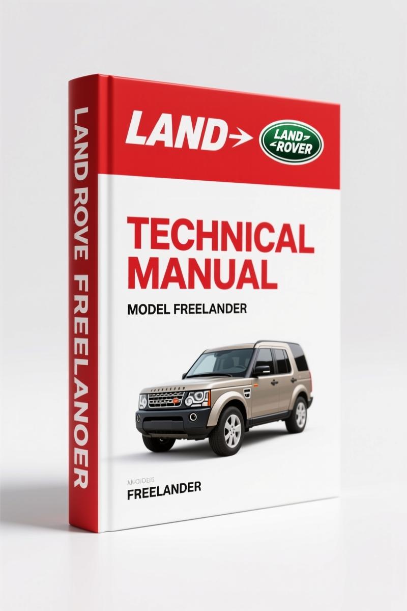
Land Rover Freelander 2000 Wiring Diagram – 132 Pages of Electrical Circuits
Original price was: $23.70.$15.00Current price is: $15.00.
OEM wiring diagram for Land Rover Freelander 2000. 132 pages of circuit diagrams: power distribution, engine management, fuel pump, ABS, SRS.
Description
Land Rover Freelander 2000 Wiring Diagram – Factory Electrical Circuit Manual
If you’re chasing an electrical gremlin on a 2000 Freelander and you’ve been using a third-party diagram, stop. You’re wasting time. This Land Rover Freelander 2000 Wiring Diagram is the real deal – 132 pages of factory circuit diagrams from Land Rover themselves. I’ve been an ASE Master Technician for 28 years, and I’ve seen what happens when a guy tries to trace a short using a copied schematic. The wire colors are wrong, the connector pinouts are missing, and you end up replacing parts that were fine. Save yourself that headache.
Land Rover Freelander 2000 Wiring Diagram: Factory Electrical Circuits
This is a 2nd Edition manual, printed in 2000 for the 2001 model year Freelander (LHD). It’s not a reprint or a third-party compilation – it’s the same document Land Rover dealers used. Every circuit is drawn with factory symbols and wire colors. The table of contents alone covers over 40 systems, from power distribution to the communication data buses. You get the engine compartment fuse box layout and the passenger compartment fuse box, both with amperage ratings. Earth distribution is mapped out so you can find where a ground failure is hiding.
Engine Management Wiring for Td4, K1.8, and KV6
Three engine variants appear in this manual: the Td4 diesel, the K1.8 petrol, and the KV6. Each has its own dedicated engine management section. You’ll find the fuel pump circuit, the charging and starting diagrams, and the ECU pinouts. The cruise control wiring is included for the Td4 and KV6 – the K1.8 didn’t get it from the factory. If you need to diagnose a no-start on a Td4, the immobiliser and engine immobilisation section (page 3.4) shows exactly how the transponder interacts with the CCU. I’ve used that section myself to trace a broken wire in the steering column.
What Systems Are Covered in the Fuel Pump and ABS Sections?
The fuel pump wiring is on its own page (15.6), separate from the engine management – that matters because the pump relay path changes with the key-off delay. The Anti-Lock Braking System (ABS) section (35.1) gives you the wheel speed sensor circuits and the modulator connections. Also included: the Electronic Automatic Transmission (EAT) diagram, the Supplementary Restraint System (SRS) airbag wiring, and the air conditioning circuits split by engine type. For the KV6 there’s a separate A/C section because the compressor clutch wiring differs from the K1.8.
Stick with Factory OEM Diagrams – Avoid Aftermarket Problems
I’ve been using factory diagrams for decades, and I can spot an aftermarket copy from a mile away. The aftermarket ones often drop critical splice locations or use generic symbols. This Land Rover manual has header joints, splices, and centre taps listed explicitly. The communication data buses (CAN, K-line) are mapped with termination resistors. If you’re working on a Freelander with a central control unit issue, the CCU section (11.1) lists every input and output pin. That kind of detail doesn’t exist in a generic wiring book. Pair this with the Land Rover Freelander 2004 Wiring Diagram if you need later model updates – but for 2000, this is the one.
Read the Power Distribution Page Carefully First
Before you dive into any system, start with the power distribution section. It shows how battery voltage flows through the engine compartment fuse box and the passenger compartment fuse box. You’ll see the fusible links, the relay positions, and the load paths. The manual uses a standard format: each circuit has a power feed, an earth return, and all in-line connectors. On the K1.8, for example, the fuel pump gets power from fuse 12 in the passenger compartment – that’s in the diagram. I’ve had DIY guys call me saying “the pump doesn’t run” – nine times out of ten they missed a blown fuse that the diagram would have shown them in two minutes.
Diagnostic Socket and Central Control Unit (CCU) Details
You’ll find the diagnostic socket wiring (10.1) and the CCU (11.1) – both essential for fault code reading and system testing. The manual also covers the rotary coupler for the steering wheel, the horns, the cigar lighter, and the accessory socket. Every exterior lamp circuit is broken into separate schematics: brake and reverse lamps, head/side/tail lamps, rear fog lamps, and direction indicators. This level of separation means you don’t have to hunt through a cluttered single-page diagram. If you need the owner-specific documents, check the Land Rover Freelander 2000 Owner’s Handbook for maintenance schedules, and the Land Rover Freelander In-Car Entertainment System User Manual for radio wiring.
Frequently Asked Questions
- Does this wiring diagram include pinout data for the ECU?
- Yes. The engine management sections list connector views and pin functions for the Td4, K1.8, and KV6 ECUs. You get wire colors and signal descriptions.
- Will this work for a 2000 Freelander with the 1.8 petrol engine?
- Absolutely. The K1.8 section covers the 1.8L engine – charging, starting, engine management, fuel pump, and cooling fan. The A/C diagram for the K1.8 is on the same page as the KV6.
- How are the fuse boxes documented?
- Both the engine compartment and passenger compartment fuse boxes are shown with full layouts. Each fuse position is numbered with its amperage rating and the circuits it feeds. The passenger compartment box is on a separate page from the engine box.
- I need the wire color codes for the rear wiper circuit. Are they in this manual?
- Yes. The Wipers and Washers section has a dedicated page for the rear wiper, including the relay and motor wiring. Wire colors are printed in English directly on the diagram (e.g., Green/White, Red/Black). No guessing.
Get the Right Tool for the Job
If you’ve ever tried to diagnose an electrical problem without a factory diagram, you know how long it can take. This manual cuts that time drastically. It’s 132 pages, OEM, and covers every system on the 2000 Freelander – from the fuel burning heater to the heated seats. For more background on how automotive wiring systems work, check Automotive Wiring on Wikipedia, and for an industry perspective see the Automotive Industry Overview. If you need the wiring diagrams for a 2004 model, the Land Rover Freelander 2004 Wiring Diagram is also available. But for your 2000, this is the one. Access the Factory Manual now.
Additional information
| Brand | Land Rover |
|---|---|
| Language | English |
4 reviews for Land Rover Freelander 2000 Wiring Diagram – 132 Pages of Electrical Circuits
You may also like…
-
Sale!
Land Rover Defender Workshop Manual – 1213 Pages of Factory Specs
Original price was: $62.80.$40.00Current price is: $40.00. -
Sale!
Land Rover Defender 2007 Electrical Schematic – 338-Page OEM Circuit Data
Original price was: $53.20.$40.00Current price is: $40.00. -
Sale!
Land Rover Freelander 2003 Wiring Diagram – Factory Electrical Schematics
Original price was: $58.95.$45.00Current price is: $45.00. -
Sale!
Land Rover Defender 1996 Workshop Manual – Factory Specs for 300Tdi
Original price was: $63.20.$40.00Current price is: $40.00.
Related products
-
Sale!

Service Manual – International HS 2.8L Engine – 130 Pages of Factory Specs
Original price was: $56.40.$40.00Current price is: $40.00. -
Sale!

1994 Troubleshooting Manual – International 1000-4000 FBC
Original price was: $60.00.$50.00Current price is: $50.00. -
Sale!

2004 Acura TSX Wiring Diagram – 73-Page Factory Electrical Schematics
Original price was: $15.88.$9.99Current price is: $9.99. -
Sale!

1989 Service Manual – International 2000-8000 Electrical Systems
Original price was: $72.00.$50.00Current price is: $50.00.
Thomas B. –
Five stars! Immediate link after checkout process. Every wiring layout is provided for Land Rover Rover. I will recommend this shop to others.
John S. –
This is just what I required. It is very easy to read on my iPad without losing quality. A must-have for any Land Rover Rover DIYer doing maintenance. I will definitely buy again.
Richard G. –
This is just what I needed. The PDF looks clean. Contains detailed schematics for Land Rover. Highly recommended for mechanics.
pro_mechanic –
Perfect factory service manual. Quick access after checkout process. Every torque spec is included for Land Rover Rover. Worth every penny.