
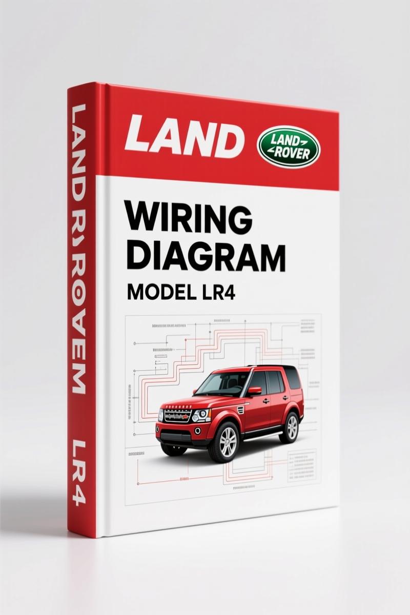
Land Rover Discovery 4 LR4 Wiring Diagram – 172 Pages OEM Spec
Original price was: $32.00.$25.00Current price is: $25.00.
OEM Land Rover Discovery 4 / LR4 Wiring Diagram – 172 pages covering suspension, transmission, brake, and all electrical systems.
Description
Land Rover Discovery 4, LR4 Wiring Diagram – Factory Electrical Schematics
You’ve got a Land Rover Discovery 4, LR4 Wiring Diagram job sitting on the rack, and some aftermarket printout says pin 12 goes to the brake light switch. Three hours later you’re staring at a fried module and a customer who’s watching the clock. That’s what happens when you trust generic wiring diagrams. I’ve seen it more times than I’ve seen stripped bolts. This manual is the real deal – OEM factory electrical schematics, 172 pages, published by Land Rover Technical Communications (part no. JLR 16 22 21_1E). It’s the same binder that rolls off the dealer’s printer. No reprints, no guesswork.
Why Factory Wiring Diagrams Beat Aftermarket
Aftermarket wiring diagrams leave out ground distribution details, splice locations, and pin-out variations between 6-speed and 8-speed transmissions. This manual doesn’t. It starts with Using This Publication – explains how to read the circuit sheet numbering and understand the diagrams. That section alone saves you from chasing phantom opens. The 172 pages cover every electrical system on the Discovery 4 and LR4 (LHD) from VIN 596988 onward. You get the Land Rover factory color codes, connector views, and component locations. There is no third-party interpretation. If the wire is brown with a yellow tracer, the manual says brown/yellow. Not “brn/ylw.” Factory spec.
Suspension and Brake Systems: Wiring You Can’t Guess
Section 204-05 covers the Vehicle Dynamic Suspension – both 6-speed and 8-speed transmission variants. That’s the air suspension wiring, ride height sensors, compressor relay circuits. If you miswire the compressor supply, you get a sagged rear end and a warning light. Section 206-09 addresses the Anti-Lock Control (ABS) – wheel speed sensor circuits, modulator valves, and the electronic brake distribution. Brake system wiring is not the place to experiment. Section 205-02 covers the rear drive axle and differential wiring – locker motors and differential temperature sensors. You get the real pin numbers.
Transmission Sections: 6-Speed and 8-Speed Wiring
Section 307-01 Automatic Transmission splits into 6-speed and 8-speed sub-sections. The Transmission control module wiring, shift solenoid circuits, and torque converter clutch lockup wiring are all laid out by transmission type. If you try to use the 6-speed diagram on an 8-speed car, you’ll be pulling the valve body for nothing. The manual also includes transmission wiring for the DV6 (2.7L) diesel engine variant. That’s a separate subsection inside 307-01. Pay attention to which engine and transmission combo you have before you start poking around.
Starting System and Engine Controls (DV6 and PV8)
Section 303-06 gives you the Starting System wiring – starter motor circuit, ignition switch feed, starter relay pin-out. Section 303-14B covers Electronic Engine Controls – DV6 (3.0L). Section 303-14E covers the PV8 (5.0L) gasoline engine. Each includes the 6-speed and 8-speed transmission variants. Section 303-14 also includes the older DV6 (2.7L) engine controls. That means you have crankshaft position sensor, camshaft position sensor, injector driver circuits, and the ECM power supply wiring. For a 5.0L complaint that cranks but won’t start, go straight to page on the 303-14E section – the ECM power and ground distribution is there.
Module Communications and Anti-Theft
Section 418-00 covers the Module Communications Network – CAN bus (high speed and medium speed), MOST fiber optic, and the diagnostic socket pin-out. If your scan tool won’t communicate, you need to know which CAN bus has lost a termination resistor. Section 419-01 covers Anti-Theft System – keyless entry, passive start, and active alarm wiring. That includes the door lock actuator circuits and immobilizer antenna ring wiring. Miswire the passive start antenna and the car won’t recognize the key fob. The manual shows the exact circuit paths.
FAQ
- Does this manual cover the fuel tank wiring?
- Yes, section 310-01 Fuel Tank and Fuel Lines covers the fuel pump module wiring, sender unit, and vent valve circuits.
- How do I interpret the circuit diagrams in this manual?
- The manual includes a full section called “Understanding the circuit diagrams” (pages xi-xii). It explains the numbering system: each circuit sheet is numbered by system and component. For example, sheet 204-05-1 starts the suspension diagrams. Connectors are referenced with numerical pin numbers and wire color codes per Land Rover’s factory standard. You also get a complete abbreviations list. If you’re not used to factory schematics, read that section before you touch the multimeter. It’s 4 pages that will keep you from misreading a ground symbol as a power feed.
I’ve been turning wrenches for 28 years. I don’t use aftermarket wiring diagrams for anything beyond a quick reference. When a job pays warranty time, you need the right pin-out the first time. This is that manual. If you’re working on a Discovery 4 or LR4, you should have this PDF open on your tablet or printed out on the bench. Check out the related manuals for other Land Rover models: Land-rover DEFENDER V8i 1998 Wiring Diagram – OEM 42-Page Manual”>Land-rover DEFENDER V8i 1998 Wiring Diagram – OEM 42-Page Manual, Land-rover DEFENDER 1998 Wiring Diagram – Factory Electrical Schematics”>Land-rover DEFENDER 1998 Wiring Diagram – Factory Electrical Schematics, and Land-rover DEFENDER 90-NAS 1996 Wiring Diagram – OEM 40-Page PDF”>Land-rover DEFENDER 90-NAS 1996 Wiring Diagram – OEM 40-Page PDF. For more context on reading automotive wiring fundamentals, see Automotive Wiring”>Automotive Wiring and Automotive Wiring”>Automotive Wiring on Wikipedia. Access the Factory Manual and keep it on your hard drive – you’ll thank yourself the first time a 5.0L LR4 shows up with a no-crank complaint.
Additional information
| Brand | Land Rover |
|---|---|
| Language | English |
2 reviews for Land Rover Discovery 4 LR4 Wiring Diagram – 172 Pages OEM Spec
You may also like…
-
Sale!
Land Rover Defender Workshop Manual – 1213 Pages of Factory Specs
Original price was: $62.80.$40.00Current price is: $40.00. -
Sale!
Land Rover Defender 2007 Electrical Schematic – 338-Page OEM Circuit Data
Original price was: $53.20.$40.00Current price is: $40.00. -
Sale!
Land Rover Freelander 2003 Wiring Diagram – Factory Electrical Schematics
Original price was: $58.95.$45.00Current price is: $45.00. -
Sale!
Land Rover Defender 1996 Workshop Manual – Factory Specs for 300Tdi
Original price was: $63.20.$40.00Current price is: $40.00.
Related products
-
Sale!

1991 Electrical Schematic – 112-Page OEM Wiring Diagram for International 1000-3000 Series
Original price was: $22.75.$17.50Current price is: $17.50. -
Sale!
1996 Operators Manual – International 1000-4000 Series (246 pages)
Original price was: $15.28.$9.99Current price is: $9.99. -
Sale!

1989 Service Manual – International 2000-8000 Electrical Systems
Original price was: $72.00.$50.00Current price is: $50.00. -
Sale!
1993 Operators Manual – International Bus 1000-3000 OEM Specs
Original price was: $12.30.$7.99Current price is: $7.99.
Richard G. –
Five stars! The file is high resolution. A must-have for any Land Rover Rover owner doing repairs. I will definitely buy again.
John S. –
Perfect workshop guide. Instant access after payment. A must-have for any Land Rover Rover DIYer doing repairs. Saved my weekend project! Thank you.