
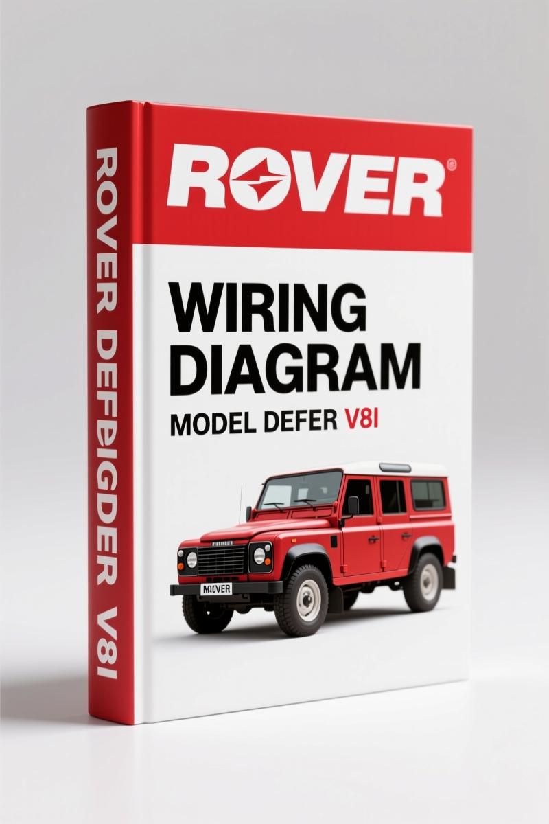
Land-rover DEFENDER V8i 1998 Wiring Diagram – 42 Pages
Original price was: $20.48.$16.00Current price is: $16.00.
OEM wiring diagram for Land-rover DEFENDER V8i 1998. 42 pages of colour-coded circuits, GEMS engine management, and brake lamp schematics.
Description
Land-rover DEFENDER V8i 1998 Wiring Diagram – Factory Electrical Schematics
You’ve got a 1998 Land-rover DEFENDER V8i 1998 Wiring Diagram on the bench. It’s a V8. It’s a Defender. That means someone’s been into the harness before you – probably with a roll of electrical tape and a prayer. Aftermarket wiring diagrams are a gamble. Wire colors shift, pinouts lie, and half the time you’re tracing a ghost. This is the real thing: 42 pages of factory-issued circuit diagrams from Rover Group Limited, published in 1998. Every node, every splice, every fuse location is where the engineers left it. No guesswork.
Page count: 42. That’s tight. Means every page is loaded with actual schematics, not filler. The manual covers colour codes, how to read the diagrams, power distribution, earth distribution, engine immobilisation, anti-theft alarm, charging and starting for the V8, diagnostic socket, and the GEMS engine management system. If you’re chasing a crank/no-start on a GEMS-equipped Defender, this is the only map you need.
How to Use the Circuit Diagrams
Open to page 3 and you get the full colour code table. Land-rover uses a 12-wire system: black, green, pink, light green, brown, orange, purple, red, slate (grey), blue, white, yellow. Each wire has a single-letter code. For example, ‘N’ is brown, ‘U’ is blue. The European-facing manual includes Dutch, German, Spanish, French, Italian, and Portuguese translations of the colour codes – handy if you’re working on an import. The diagrams themselves follow a standard flow: from power source through fuse, switch, load, and ground. You trace the circuit left to right. If you’re used to aftermarket junk that skips the ground path, this will feel like a breath of fresh air.
Power Distribution and Earth Distribution
Two sections you’ll reference constantly: POWER DISTRIBUTION (fuse boxes and headers) and EARTH DISTRIBUTION. The Electrical system in a Defender is notorious for corrosion at earth points. The manual shows each earth location explicitly – not just a generic “ground at chassis”. Fuse box layouts are detailed with header numbers. If you’ve got a dead interior light, start at the fuse box diagram on page 1.1 and work your way to the earth point on the bulkhead. Saves hours of pulling trim.
Engine Management – GEMS
GEMS stands for GEMS Engine Management System. It’s the Bosch-derived system used on the 1998 V8i. The manual dedicates a full section (20.1) to the GEMS ECU pinout, sensor inputs, and injector circuits. If you’re chasing a misfire or a no-start, the diagnostic socket section (10.1) shows you which pins to back-probe for crank and cam signals. The Engine management diagrams are drawn with component locations – you’ll see the MAF sensor, IAT, coolant temp, and throttle position sensor all mapped. No more guessing which wire is the signal return.
Brake and Reverse Lamps Circuit
EXTERIOR LAMPS includes the Brake and reverse lamps circuit (43.1). The Defender’s brake light switch is a common failure point. The diagram shows the switch feed from fuse 11, through the brake pedal switch, then to the stop lamp bulbs. It also notes the wire colour change at the switch. Cross-reference with the colour code table and you’ll have the problem isolated in ten minutes. The reverse lamp circuit runs through the gearbox switch – the manual shows the exact path, including the diode pack that prevents backfeed. That diode is often missing on aftermarket copies.
Why OEM Wiring Diagrams Matter
I’ve seen techs waste a full day because a third-party diagram had the wrong wire colour for the starter solenoid. That doesn’t happen with this manual. It’s a direct scan from the original Rover Technical Communication print. The file name – Rover_DEFENDER_V8i_1998_Wiring_Diagram_en-de-fr-es-37511014471.pdf – tells you it’s the multi-language European edition. That means the diagrams are identical to what the factory technicians had in 1998. No revisions, no “interpretations”. If you’re serious about electrical diagnostics, you need the OEM source. For more on reading automotive wiring principles, see Automotive Wiring on Wikipedia. For context on the Land-rover brand’s history, check Automotive Industry Overview.
Who Needs This Manual?
DIY mechanics working on a 1998 Defender V8i. Restoration shops that need factory-correct circuits. Off-road enthusiasts who can’t afford a tow because of a wiring fault. If you’re swapping a GEMS-equipped engine into a different chassis, the pinout data alone is worth the price. The manual is 42 pages – print it, laminate key pages, keep it in the glovebox. You’ll use it every time a fuse blows, a lamp fails, or the engine immobiliser locks you out.
Related manuals you might need: Rover DEFENDER 1999 Electrical Circuit Diagrams for the next model year, Rover DEFENDER 90-NAS 1996 Electrical Circuit Diagrams for the North American version, and Land-rover Freelander 1999 User Manual – Softback & Hardback Guide for a different platform.
FAQ – Land-rover DEFENDER V8i 1998 Wiring Diagram
- Does this manual cover the fuel injection system?
- Yes. The ENGINE MANAGEMENT – GEMS section (20.1) includes injector circuits, fuel pump relay control, and the ECU power supply. The diagnostic socket (10.1) shows how to read fault codes.
- Are the colour codes in English?
- Yes. The table on page 3 lists each code with English colour names. The page also includes translations for Dutch, German, French, Italian, Spanish, and Portuguese.
- What about the air conditioning circuit?
- Covered in section 38.1. Includes compressor relay, thermostatic switch, and blower motor connections. The diagram shows the interlock with the heater circuit (39.1).
- Can I use this for a 1997 Defender V8i?
- Mostly. The GEMS system was introduced in 1996, but early 1997 models had slight wiring differences. You’ll want the 1997-specific diagram. This 1998 manual is a close match but always verify the ECU pinout against your vehicle’s build date.
Stop chasing wires with a multimeter and a prayer. Access the Factory Manual and get the actual circuit diagrams that Land-rover trusted. Forty-two pages of direct, no-nonsense electrical schematics – exactly what you need to fix a Defender’s electrical gremlins the right way.
Additional information
| Brand | Land-rover |
|---|---|
| Language | English |
3 reviews for Land-rover DEFENDER V8i 1998 Wiring Diagram – 42 Pages
You may also like…
-
Sale!
Land-rover 200, 114, 214, 414, 216 2001 Repair Manual – Factory Specs
Original price was: $44.70.$30.00Current price is: $30.00. -
Sale!
Land-rover 101 Repair Manual – Factory MoD Specs for 1 Tonne 4×4
Original price was: $66.60.$45.00Current price is: $45.00. -
Sale!
Land-rover 214, 414 1997 Service Manual – OEM Factory Specs
Original price was: $33.50.$25.00Current price is: $25.00. -
Sale!
Land-rover 25, 45, 220, 420, 620 1999 Repair Manual – Factory Specifications
Original price was: $37.80.$30.00Current price is: $30.00.
Related products
-
Sale!

1993 Operators Manual – International Bus 1000-3000 OEM Specs
Original price was: $12.30.$7.99Current price is: $7.99. -
Sale!

2005 Parts Catalog – International NGD 3.0 L Engine (77 pages)
Original price was: $44.70.$30.00Current price is: $30.00. -
Sale!

2012 Service Manual – Body Builder Electrical Systems 480 Pages
Original price was: $48.28.$34.00Current price is: $34.00. -
Sale!
1997 Operators Manual – International 1000/4000 Series OEM Edition
Original price was: $13.49.$9.99Current price is: $9.99.
pro_mechanic –
Five stars! Immediate link after checkout. A must-have for any Land-rover DEFENDER owner doing maintenance. Saves me hundreds of time.
James L. –
I am very pleased with this purchase. The document quality is excellent. A must-have for any Land-rover DEFENDER DIYer doing maintenance. Saves me so much money.
David K. –
Perfect factory service manual. Instant access after checkout process. It guided me to repair my Land-rover DEFENDER electrical system. Saved my weekend project! Thanks.