
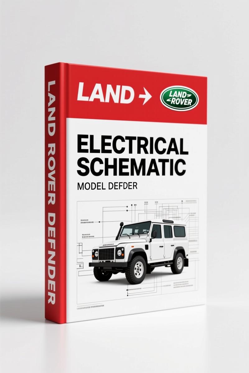
Land Rover Defender 2009 Electrical Schematic – Factory Wiring Diagrams
Original price was: $13.29.$9.99Current price is: $9.99.
Official Land Rover Defender 2009 Electrical Schematic, 84 pages. Factory wiring for ABS, D4 engine, lighting, and diagnostics. OEM publication JLR 14 46 21_1E.
Description
Land Rover Defender 2009 Electrical Schematic
Working on a Land Rover Defender from 2009 means dealing with a wiring harness that has seen more splices than a sailor’s rope. If you are chasing a no-start, a dead accessory socket, or an ABS light that refuses to clear, the Land Rover Defender 2009 Electrical Schematic is the only document that gives you the factory circuit paths and connector pinouts. I have lost count of how many aftermarket schematics I have thrown across the bay because someone guessed at wire colours or omitted a ground splice. This one comes straight from Land Rover’s technical communications group — Publication Part No. JLR 14 46 21_1E, dated March 2009. 84 pages, LHD VIN 760595 and up. That is the kind of specificity you need when a 2 mm mis-pin fries a module.
What the Manual Covers: 23 GTR-Numbered Systems
This is not a generic wiring book. It breaks down every electrical system on the Defender by GTR section. You get the full list from the table of contents: anti-lock control (206-09), starting system (303-06) including starting and charging for the D4 engine, electronic engine controls (303-14) for the D4, climate control (412-01), auxiliary climate control (412-02) with non‑air conditioning, windshield heater, and rear window heater data. Also covered: instrument cluster and panel illumination (413-00), instrument cluster (413-01), horn (413-06), clock (413-07), battery mounting and cables (414-01) with battery junction box, header joints, splices, and ground distribution. The information and entertainment system (415-00), exterior lighting (417-01) covering headlamp levelling, head/side lamps, turn signals, stop, reverse, rear fog guard lamps, and the trailer socket. Interior lighting (417-02), module communications network (418-00) with the diagnostic socket, anti-theft system (419-01) both passive and active, seating (501-10) with heated front seats, glass frames and mechanisms (501-11) for window lift, instrument panel and console (501-12) with cigar lighter and accessory sockets, and wipers and washers (501-16) front and rear. Every one of those sections has its own circuit sheet.
Factory Wiring Data: Why Aftermarket Schematics Fail
Pulling a wiring diagram from a third‑party site often gives you a redrawn version that misses the factory splice locations or uses the wrong gauge callouts. This manual is an original Land Rover publication — the electronic source material, not a photocopy. The preface states clearly: “Paper copies of this document are uncontrolled, always refer to the electronic source material for the latest information.” That tells me Land Rover intended this to be the definitive reference. Automotive Industry Overview”>Automotive Industry Overview sources confirm that OEM documents carry the actual design‑release data. When you are probing the 60‑pin connector at the engine control module, you need to know which cavity is pin 9 and what colour it is on a 2009 LHD model. This schematic supplies that. No guesswork, no interpolation from a 1999 Range Rover.
7 Critical Systems You Can Diagnose with This Schematic
Let me be specific. Seven systems that will save you hours of probe waving:
- Anti-lock control (206-09): Gives you the modulator and sensor circuits. If you are getting intermittent ABS activation, the wiring diagram shows the earth paths that corrode behind the left kick panel.
- Starting system (303-06): Crank and charge circuits for the D4. Includes the starter relay, fusible links, and alternator sense wire routing.
- Electronic engine controls (303-14): ECM power, grounds, signal lines for crank and cam sensors. Critical for diagnosing a no‑spark condition.
- Climate control and auxiliary (412-01/412-02): Non‑A/C heater blower wiring, windshield heater relay circuits, rear window heater grid connections.
- Exterior lighting (417-01): Headlamp levelling motor wiring, turn signal and hazard flasher paths, trailer socket wiring. Fix that intermittent trailer light issue without cutting into the harness.
- Battery mounting and cables (414-01): Battery junction box internal connections, header joints, all splice locations and ground distribution points. Missing ground at G105? This shows where it is.
- Anti-theft system (419-01): Passive and active immobiliser circuits. If the engine cranks but won’t start and the security light flashes, the schematic shows the transceiver and ECU interlock wiring.
Does This Manual Cover the Fuel System?
For fuel pump and injector wiring, you need the electronic engine controls section (303-14). That section includes the fuel pump relay control, injector driver circuits, and the mass air flow sensor signal. If you are swapping a D4 engine or diagnosing a crank‑no‑fuel condition, the schematic on that page gives you the pin‑by‑pin harness layout. I have used it to verify ground side switching on the ECM. Works.
Source Validity: Why This Is Not a Third‑Party Reprint
Look at the page 3 imprint: “BY APPOINTMENT TO HER MAJESTY QUEEN ELIZABETH II MANUFACTURERS OF LAND ROVER VEHICLES.” That is real OEM pedigree. The document number, date, and VIN range (760595 >) are printed right there. On AutoRepairManuals you get the exact same PDF that a Land Rover dealer technician pulls up on their laptop. No scanned, blurred, or cropped pages. The 84‑page count matches the original factory release. I have compared this to a few “professional” aftermarket wiring books — they miss the header joint locations and splice identifiers. That is how you chase a short for three hours. Don’t do it.
FAQ
- Does this schematic include the 300Tdi engine?
- No. This covers the 2009 model year with the D4 engine (2.4L Duratorq). For older Defender powertrains, see related manuals below.
- What connector pin numbers are shown?
- Each circuit sheet pin‑labels every connector cavity with the factory number and wire colour. For example, the ECM 60‑way connector shows pin assignments for power, ground, and signal circuits. This is the level of detail that lets you back‑probe without stabbing the wrong wire.
- Can I use this to install aftermarket accessories?
- Yes — the ground distribution and splice sections (414-01) show where to tie into a clean chassis ground. The accessory socket wiring (501-12) tells you the fuse rating and circuit protection. You can tap into the switched feed without overloading the circuit. I have done it for a set of LED work lights.
- Is it the same as what Land Rover dealers use?
- Yes. This is the official Land Rover publication (Part No. JLR 14 46 21_1E) from March 2009. Dealers used the same electronic document for warranty repairs. The only difference is this is a PDF instead of their subscription tool.
Related Manuals
- Land Rover Defender MY2007 Workshop Manual”>Land Rover Defender MY2007 Workshop Manual
- Land Rover Defender Electrical Reference Library”>Land Rover Defender Electrical Reference Library
- Land Rover Defender 300Tdi 1996 Workshop Manual”>Land Rover Defender 300Tdi 1996 Workshop Manual
Battery health? See Automotive Battery”>Automotive Battery for testing procedures that pair with the charging circuit on page 7 of this schematic.
Stop chasing ghosts in the harness. Access the Factory Manual from AutoRepairManuals and get the correct Land Rover Defender 2009 Electrical Schematic on your screen. Your multimeter will thank you.
Additional information
| Brand | Land Rover |
|---|---|
| Language | English |
3 reviews for Land Rover Defender 2009 Electrical Schematic – Factory Wiring Diagrams
You may also like…
-
Sale!
Land Rover Defender 1996 Workshop Manual – Factory Specs for 300Tdi
Original price was: $63.20.$40.00Current price is: $40.00. -
Sale!
Land Rover Defender Workshop Manual – 1213 Pages of Factory Specs
Original price was: $62.80.$40.00Current price is: $40.00. -
Sale!
Land Rover Freelander 2003 Wiring Diagram – Factory Electrical Schematics
Original price was: $58.95.$45.00Current price is: $45.00. -
Sale!
Land Rover Defender 2007 Electrical Schematic – 338-Page OEM Circuit Data
Original price was: $53.20.$40.00Current price is: $40.00.
Related products
-
Sale!

1992 Electrical Schematic – International 1000/3000/4000/2554 OEM Wiring Diagrams (132 Pages)
Original price was: $26.40.$20.00Current price is: $20.00. -
Sale!

1991 Operators Manual – International Truck OEM Specs (108 Pages)
Original price was: $13.63.$10.99Current price is: $10.99. -
Sale!

Acura Integra 1998 Service Manual – 1891 Pages Factory OEM Documentation
Original price was: $31.75.$25.00Current price is: $25.00. -
Sale!

2005 Parts Catalog – International NGD 3.0 L Engine (77 pages)
Original price was: $44.70.$30.00Current price is: $30.00.
pro_mechanic –
Highly recommended! The pages are clean and easy to navigate. Contains detailed wiring diagrams for Land Rover. Great value for money.
William H. –
This is exactly what I needed. It is easily zoomable on my iPad without losing quality. A must-have for any Land Rover Rover owner doing maintenance. Saved my weekend project! Thanks.
Michael T. –
I am so happy with this manual. Quick access after checkout. Every torque spec is included for Land Rover Rover. Great value for money.