
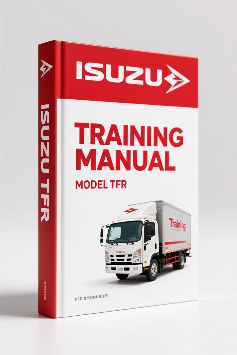
Isuzu TFR, TFS Training Manual – 4JH1-T Engine V5 System
Original price was: $37.50.$25.00Current price is: $25.00.
Isuzu TFR, TFS Training Manual – 79 pages covering 4JH1-T engine V5 system, ECM, electrical diagnostics, and Tech 2 procedure.
Description
Isuzu TFR, TFS Training Manual – 4JH1-T Engine Management System
If you’ve ever bought an aftermarket “manual” for a diesel and found the wiring diagram looks like a third-grader’s doodle, you know the pain. Guessing the ECM pinout on a 4JH1-T will cost you a weekend and a fried ECU. That’s why you need the real thing: a factory Isuzu TFR, TFS Training Manual – the exact document Isuzu used to train techs in Thailand for the 2003-2004 model years. This is not a reprint or a scanned copy of some generic book. 79 pages, original file date 2003–2004, and every spec comes from Isuzu Motors Limited.
4JH1-T Engine Management System: One 79-Page Document to Own
This manual covers the heart of the TFR and TFS: the 4JH1-T direct injection diesel with eight overhead valves and a Denso V5 electronic injection pump that pushes injection pressure up to 100 MPa. Page 1 states it’s for service training, and the entire document is built around the V5 pump’s electronic controls – not a generic diesel overview. You get the system outline, the ECM functions, the Electrical Drive Unit (EDU), the breaker box, and connector pin assignments. Want to know what pin on the ECM sends the spill valve signal? It’s in here. No hunting through internet forums.
ECM Connector Pin Assignments and Output Signals
Page 3 details the feature of the V5 injection pump – the solenoid spill valve (SPV) that replaces the old mechanical control sleeve, and the pump ROM that stores pump-specific data. The ECM uses signals from the crankshaft position sensor, camshaft position sensor, throttle position sensor, fuel temperature sensor, and manifold absolute pressure sensor to calculate injection timing and quantity. The manual lists every pin assignment for the ECM and EDU connectors. If you’re swapping an engine or chasing a no-start, these pinouts are the difference between a repair and a parts shotgun.
Fuel Injection Timing Control: TCV and Spill Valve Operation
The timing control valve (TCV) is the actuator that adjusts injection timing by moving the roller ring. The manual walks through the injection timing control method – it even shows how the ECM calculates fuel injection timing based on engine speed and load. The solenoid spill valve opening timing is explained in the Fuel Injection Quantity Control section. You get the logic behind the numbers, not just a table of values. This is training material, so it tells you why the ECM commands a certain spill valve duty cycle, not just the spec.
Diagnosis with TECH 2: DTCs and Scan Data
If the engine runs rough or the check engine light is on, the manual dedicates a full section to diagnosis with the TECH 2 scan tool. It covers what to do when no codes are set, how to connect the TECH 2, the operating flowchart, and typical scan data definitions. The ECM Diagnostic Trouble Code (DTC) table lists every code, the circuit or component involved, and the likely cause. There’s also a section on multiple DTC sets and troubleshooting aids – the kind of info that saves you from replacing a sensor that was fine because you misread the ground circuit. For symptom diagnosis, you get preliminary checks, visual/physical checks, and guidance on intermittent faults. This is not a “check engine light” generic guide; it’s a factory procedure.
Wiring Diagrams and Harness Locations
Electrical issues are the most time-consuming part of any diesel repair. This manual includes a full wiring diagram for the Engine Control Module (ECM), along with relay, fuse, and slow-blow fuse locations. Electrical harness locations are mapped so you can trace a short without pulling the entire dashboard. If you’re dealing with an intermittent fault on the EGR system – the manual covers the EGR VSV, EGR EVRV, and EGR pressure sensor – you need the wiring. No aftermarket diagram will show the correct wire colors or pin numbers for a 2003–2004 TFR/TFS. This one does, because it was printed by Isuzu for the actual production vehicle.
Isuzu TFR, TFS Training Manual: Why Factory Specs Matter
Aftermarket documentation for the Isuzu 4JH1-T often merges data from different years or engines, mixing up the V5 pump with older mechanical systems. This manual is specific to the 2003-2004 TFR and TFS with the 4JH1-T engine. The pump ROM data, the ECM programming, and the EDU driver specs are model-year exact. If you try to use a generic “Isuzu diesel manual” you risk setting injection timing with incorrect reference points or misdiagnosing a camshaft position sensor signal because the oscilloscope pattern doesn’t match. Factory training manuals eliminate that risk. They also include the special tools list and check sheet that techs used during training – practical aids when you’re working on a customer’s truck or your own project.
Related manuals that complement this one include the ISUZU 4JJ1-TC Engine 2005 Service Training Manual”>ISUZU 4JJ1-TC Engine 2005 Service Training Manual for the next generation, the Isuzu TFR/TFS, UCR/UCS Training Manual – 4JJ1-TC Engine”>Isuzu TFR/TFS, UCR/UCS Training Manual – 4JJ1-TC Engine, and the Isuzu 6HK1 4HK1 2008 Training Manual – Diagnostic & Drivability”>Isuzu 6HK1 4HK1 2008 Training Manual – Diagnostic & Drivability if you work on larger Isuzu diesel engines. For broader context on diesel engine management systems, see the Automotive Industry Overview and Automotive Industry Overview”>Automotive Industry Overview (external reference).
- Does this manual cover the 2004 Isuzu TFS with the 4JH1-T engine?
- Yes. The manual explicitly states application for 2003-2004 TFR/TFS in Thailand. All engine management specs – ECM pinouts, sensor resistances, injection timing control, and DTCs – match that exact production run.
- Are torque values for the cylinder head or injection pump given in this manual?
- No. This is a training manual focused on system operation and diagnosis, not a service repair manual. It does not list head bolt torque sequences or component tightening specs. You would use this alongside the factory service manual for repair procedures. It covers the V5 pump theory, ECM signals, and TECH 2 diagnosis in depth – exactly what you need to understand why the system behaves as it does.
Stop fighting with aftermarket garbage that leaves you guessing. Access the Factory Manual and get the same training material Isuzu techs used. No shortcuts, no missing pages – just 79 pages of real documentation for the 4JH1-T engine in your TFR or TFS.
Additional information
| Brand | Isuzu |
|---|---|
| Language | English |
2 reviews for Isuzu TFR, TFS Training Manual – 4JH1-T Engine V5 System
You may also like…
-
Sale!
Isuzu FRR WT5500 2002 Service Manual | Factory Specs
Original price was: $92.40.$60.00Current price is: $60.00. -
Sale!
Isuzu FRR 1997 Service Manual – 755 Pages of Factory Specs
Original price was: $85.80.$65.00Current price is: $65.00. -
Sale!
Isuzu NPR, W3500, NQR, NPR-HD, NRR 2006 Service Manual – 37 Pages
Original price was: $93.00.$60.00Current price is: $60.00. -
Sale!
Isuzu AA-6SD1T Workshop Manual – 243 Pages of OEM Engine Service Data
Original price was: $89.70.$65.00Current price is: $65.00.
Related products
-
Sale!

Acura NSX 1991 Service Manual – 1420 Pages OEM
Original price was: $102.05.$65.00Current price is: $65.00. -
Sale!

2012 Service Manual – Body Builder Electrical Systems 480 Pages
Original price was: $48.28.$34.00Current price is: $34.00. -
Sale!

1991 Electrical Schematic – 112-Page OEM Wiring Diagram for International 1000-3000 Series
Original price was: $22.75.$17.50Current price is: $17.50. -
Sale!

1989 Service Manual – International 2000-8000 Electrical Systems
Original price was: $72.00.$50.00Current price is: $50.00.
Michael T. –
I am so happy with this manual. It is easily zoomable on my laptop without blur. Contains clear bolt torque specs for Isuzu. Worth every penny.
diy_master –
This is exactly what I was looking for. The file is very clear. It assisted me to rebuild my Isuzu TFR, transmission. Saves me hundreds of time.