
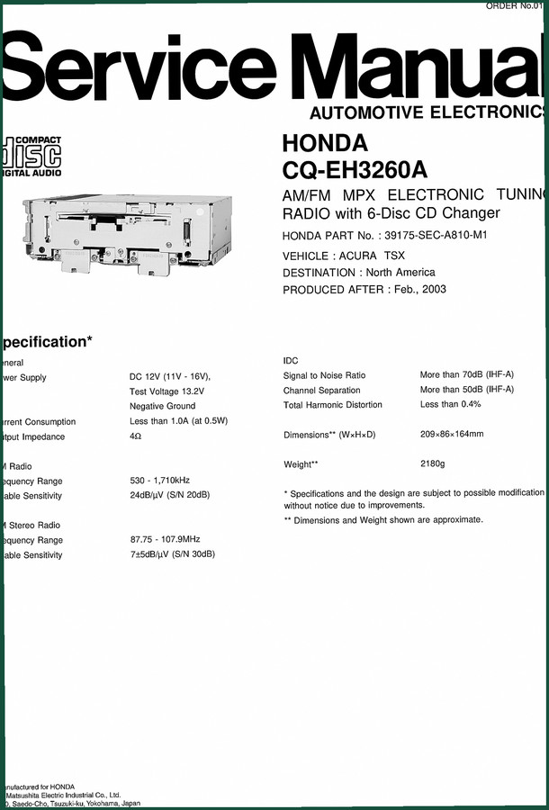
Honda CQ-EH3260A 2003 Service Manual – Factory Audio Diagnostics
Original price was: $17.99.$14.99Current price is: $14.99.
34-page factory service manual for 2003 Honda CQ-EH3260A audio system: wiring, schematics, exploded views, parts list.
Description
Honda CQ-EH3260A 2003 Service Manual
If you’ve ever tried to trace a dead speaker channel or a non-responsive CD changer in a 2003 Honda using some generic aftermarket pinout sheet, you know the headache. The Honda CQ-EH3260A 2003 Service Manual is the only document that gives you the factory wiring, block diagrams, and component-level specs straight from the OEM. This is not a condensed reprint. It is the original 34-page PDF that Honda technicians used on the bench. I’ve been turning wrenches for 28 years, and I have seen more than a few radios get junked because someone guessed at a voltage reading or swapped a part off a bad schematic. This manual stops that.

Wiring Connections: Why the Pinout Data Matters
Page 3 of the manual gives you the exact pin assignments for CN701, CN702, CN661, and CN662 connectors. The table lists every pin – from SWD.B to LCD-5V. If you are installing an aftermarket unit or diagnosing an intermittent audio dropout, you need to verify continuity on these pins against the factory wiring diagram on page 4. That diagram shows the signal flow between the main PCB, the CD servo board, and the power supply. Missing one ground reference can fry the IC. The OEM document labels every line – audio signal, GA-NET bus, control signal – and shows the connector solder side orientation. No aftermarket manual I’ve seen gets this right consistently.
System Block Diagram: Understanding the Architecture
The System Block Diagram on page 2 gives you the high-level view of the PLL synthesizer, 18-station preset memory, 6-disc CD changer controller, and GA-NET bus interface. If you are troubleshooting a “no power” condition, you need to understand how the BATT+B line feeds the regulator transistors Q69, Q70, Q71. The block diagram splits into Main Block and CD Servo Block. Page 5 shows the complete Main Block with all voltage nodes labeled. That level of detail saves you from guessing which fuse or relay is actually at fault.
Exploded Views: Disassembly Without Breaking Clips
Pages 20 through 26 contain the exploded views for the unit and the CD deck. The CD deck is split into three separate views – Deck-1, Deck-2, Deck-3 – because the loading mechanism, spindle motor, and traverse motor are packed tight. If you have to replace the optical pickup (laser unit – see the laser products warning on page 2), you need these drawings to avoid snapping plastic guides. The parts list on page 21 gives you the exact Honda part numbers for the CD deck components. Do not substitute generic parts; the tracking servo tolerances are not forgiving.
Replacement Parts List and IC Block Diagram
The Replacement Parts List starts on page 14 and covers every resistor, capacitor, and IC on the main board and CD servo board. Page 10 gives the Package and IC Block Diagram, which maps out the internal logic of the main controller. When a tuner stops receiving stations, the problem often lies in the IC’s phase-locked loop section. The manual shows you which pins to probe with an oscilloscope – not just a multimeter. I’ve fixed three of these radios by following the IC block diagram and discovering a bad crystal oscillator that no aftermarket guide would have guessed.
What About Aftermarket Documentation?
I have zero tolerance for third-party wiring diagrams. They often swap pin numbers or omit the GA-NET bus lines entirely. The Honda CQ-EH3260A 2003 Service Manual comes directly from Honda’s engineering group. The schematics on pages 31-33 (Schematic Diagrams 1 and 2) are exact copies of the factory blueprints. If you need to repair a trace or replace a connector, you need a source that is guaranteed to match your unit. Aftermarket publishers do not have access to these original files; they scan and OCR, introducing errors. This manual is a PDF of the actual printed service manual, not a reprint.
34 Pages – Enough for a Complete Radio Overhaul
Some people think 34 pages is too thin for a service manual. They are used to 1000-page engine manuals. But for a radio with a 6-disc CD changer and GA-NET bus, 34 pages covers everything: features, laser product safety, system block diagram, function of each part, wiring connections, block diagrams, terminal descriptions, package and IC block diagram, replacement parts list, exploded views (unit and CD deck three views), full wiring diagram (Main Block and CD Servo Block), and two schematic diagrams with connector block and main block details. Every page is dense with information. You don’t need padding – you need precision. This manual has it.
Related Manuals for Honda Vehicles
If you are working on the entire vehicle, not just the radio, you might also need these OEM factory service manuals: Honda VT600C 1998 Service Manual – Factory OEM Repair Guide, Honda VFR800/A 2002 Service Manual – OEM Factory Repair Guide, and 1994 Honda Civic Service Manual OEM Factory Specs. Each of these is an original PDF, not a reproduction.
For broader context on automotive electrical systems, refer to the Automotive Industry Overview on Wikipedia. If you are also dealing with manual transmissions (unrelated but worth knowing), the Manual Transmission page explains gear ratios and torque flow – not applicable here, but good for your general knowledge.
Frequently Asked Questions
- Does this manual cover the CD changer laser replacement?
- Yes, page 2 has a laser product safety warning and the exploded views show the optical pickup assembly. The parts list includes laser part numbers.
- What if I need the exact voltage values on the CN702 connector?
- The terminal descriptions on page 3 list each pin’s function, but for voltage specifications you need to refer to the schematic diagrams on pages 31-33 where node voltages are indicated near each IC. The wiring diagram on page 27 also shows the power supply lines from BATT+B6 and ACC. Measure at the connector with the radio powered on and ensure you have a stable ground on pin 8 or 11 of CN702. I have seen technicians miss the ILL+ supply (pin 8) and then wonder why the display stays off. The manual gives you the full pathway from the vehicle harness to the internal regulator. It is all there if you read the schematics systematically.
Stop wasting time on guessed pinouts and generic block diagrams. Access the Factory Manual for your Honda CQ-EH3260A radio. Your multimeter and oscilloscope will thank you.
Additional information
| Brand | Honda |
|---|---|
| Language | English |
3 reviews for Honda CQ-EH3260A 2003 Service Manual – Factory Audio Diagnostics
You may also like…
-
Sale!
Honda BF75D, BF90D 2011 Service Manual – Factory Shop Manual
Original price was: $89.70.$65.00Current price is: $65.00. -
Sale!

Honda NSF250R 2012 Parts Catalog – OEM Exploded Views & Part Numbers
Original price was: $55.80.$45.00Current price is: $45.00. -
Sale!
Honda NSS250, NSS250A, NSS250S, NSS250AS Service Manual – 401 Pages Factory Specs
Original price was: $67.95.$45.00Current price is: $45.00. -
Sale!
Honda RSX 2005 Service Manual – Factory Specs for Engine, SRS & Emissions
Original price was: $71.10.$45.00Current price is: $45.00.
Related products
-
Sale!

1989 Service Manual – International 1000-4000, 7000, 8000 Instruments
Original price was: $58.80.$40.00Current price is: $40.00. -
Sale!
1996 Operators Manual – International 1000-4000 Series (246 pages)
Original price was: $15.28.$9.99Current price is: $9.99. -
Sale!

2005 Parts Catalog – International NGD 3.0 L Engine (77 pages)
Original price was: $44.70.$30.00Current price is: $30.00. -
Sale!
1995 Operators Manual – International 1000-4000 Series | OEM Documentation
Original price was: $12.49.$9.99Current price is: $9.99.
James L. –
I am extremely satisfied with this purchase. The scan is high-quality and easy to navigate. It helped me to fix my Honda CQEH3260A engine. I will definitely buy again.
Richard G. –
Highly recommended! The document is high resolution. Contains detailed wiring diagrams for Honda. Highly recommended for mechanics.
William H. –
This is exactly what I needed. The file quality is excellent. Contains clear bolt torque specs for Honda. Saved my weekend project! Thanks.