
Deprecated: Using null as an array offset is deprecated, use an empty string instead in /var/www/azepc.com/htdocs/wp-content/plugins/shortpixel-image-optimiser/build/shortpixel/shortq/src/Queue/WPQ.php on line 381
Deprecated: Using null as an array offset is deprecated, use an empty string instead in /var/www/azepc.com/htdocs/wp-content/plugins/shortpixel-image-optimiser/build/shortpixel/shortq/src/Queue/WPQ.php on line 381
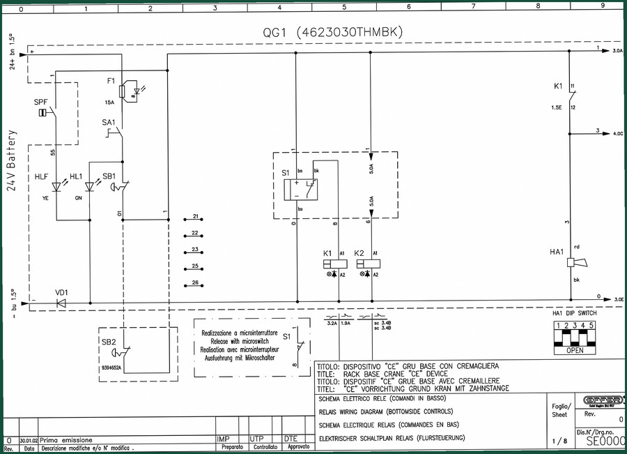
Genie QG1 Electrical Schematic – 104-Page OEM Wiring Data
Original price was: $39.00.$30.00Current price is: $30.00.
Genie QG1 Electrical Schematic: 104 pages of OEM relay wiring, main switch diagrams, and pushbutton board controls in four languages.
Description
Genie QG1 Electrical Schematic – Factory Wiring Data for Your Shop
If you’ve ever stared at a harness of corroded wires under the platform of a Genie QG1, wondering which relay feeds the horn circuit, you understand why guessing costs time and money. The Genie QG1 Electrical Schematic is 104 pages of factory-original line drawings – not a reprint, not a third-party hack. Each sheet carries the Genie part number and revision history. I keep a copy laminated next to my breakout box because when a customer’s crane won’t lift, I don’t have time to trace phantom voltage drops. This manual gives you the exact paths: battery 24+V through the main switch SA1, through the 15A fuse, to the relay coils K1, K2, K3, and out to the pushbutton board. It’s the same drawing the techs at Genie use to validate the CE device setup.
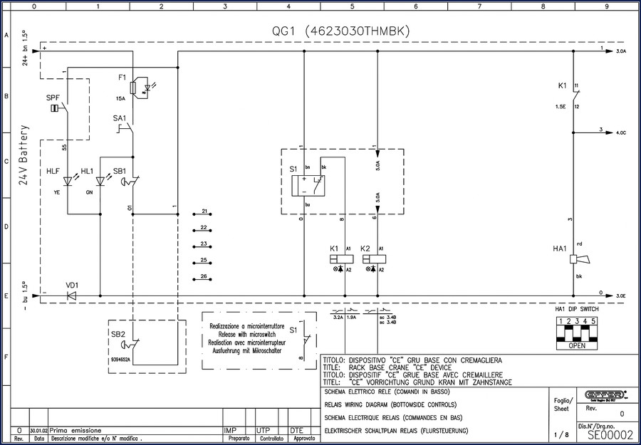
Relay Wiring Diagram – Bottom-Side Controls
Sheet 1 of the schematic covers the relay wiring for the base-level controls. You get the DIP switch HA1 with positions 1 through 5, the microswitch release circuit, and the NC/NO contact mapping for relays K1 and K2. The diagram labels each wire color – bn (brown), bk (black), rd (red), YE (yellow), GN (green) – so you can identify harness circuits without a multimeter probe hunt. Need to bypass the safety interlocks for testing? The schematic shows exactly which pins to jumper and which to leave open. Page 1 includes the title “Relay Wiring Diagram (Bottom-Side Controls)” and a 1/8 sheet number – that’s your starting point for diagnosing a dead platform.
Main Switch Wiring Diagram – Top Seat Controls
Sheet 2 shifts to the rack crane with fly jib CE device. It details the auxiliary controls box with five motor terminals (M), the 24+V feed, and the main switch SB1. The drawing shows how the 15A fuse SA1 protects the entire top-seat circuit. If your QG1 loses power when you move the joystick, start here. The schematic labels the connector pins for the aux box – 1 through 5 – so you can check continuity without pulling the whole panel. This is not a generic wiring guide; it’s the Genie factory layout with sheet revision SE000008.
Pushbutton Board and Manual Controls
Sheet 3 (2/8) covers the pushbutton board for manual controls. The diagram includes the QG10 module (6J93010) and the HLT indicator. It maps the ON switch SB1 and the 1.5° (likely cable tilt) sensor input. For technicians who prefer to test inputs before swapping controllers, this sheet saves you from replacing a good board. The 104-page set includes every control variant – base, top, and aux – so you can cross-reference wire numbers between sheets.
DIP Switch Configuration and Safety Device Layout
Sheet 4 (3/8) shows the relay wiring diagram with DIP switch HA1 settings. Positions 1-2 = EFFER, 3-2 = SPECIAL – that distinction matters when the crane is European-spec. The sheet also lists safety device codes (E4 through E12) referenced from document SE00030. If you need to verify which safety interlock is triggered, the schematic tells you which relay coil is held open. Page 5 includes the layout of devices – see the note “Vedere Dis.cod.SE00030 per Layout Dispositivi di Sicurezza.” Don’t overlook that cross-reference; it keeps you from replacing a good relay.
104 Pages – What You Actually Get
The full document runs 104 pages, not the typical 10-page aftermarket cheat sheet. Each page is a factory-original scan in English, Italian, French, and German – because these machines ship worldwide. You get the complete electrical schematic for the Genie QG1 model 4623030THMBK and 4623030THMAK, including the main switch, relay banks, pushbutton board, and the safety device reference. This is the same file that Genie distributors use to train field techs. No missing sheets, no blurred lines, no third-party redraws.
Does This Manual Cover the Entire QG1 Electrical System?
Yes. It covers the base crane CE device with rack and pinion, the fly jib version, both bottom-side and top-seat controls, and the auxiliary controls box. It does not cover engine diagnostics or hydraulic schematics – this is purely the electrical schematic. If you need the operator’s manual or service repair manual, check the related documents below.
3 Reasons to Trust This OEM Documentation
First, it carries the Genie part number on every sheet – no reprints from unknown sources. Second, the revision history (Rev. 0, Data Imp, Preparato UTP, Controllato DTE, Approvato) proves it was approved by Genie engineering. Third, the 104-page count guarantees you have the complete set, not a truncated summary. When I’m training a junior tech on relay logic, I hand them this schematic because the wire colors and pin numbers match the machine under the lift.
FAQ
- Is this a Genie factory electrical schematic or a third-party reprint?
- It is the original Genie factory file, scanned from the official document SE000008 and SE000002 series. It includes the revision stamps and part numbers.
- Can I use this to diagnose a QG1 that won’t raise the boom?
- Yes, but only for electrical faults – relay coil failure, open safety circuits, blown fuses. Start at the main switch SB1 on sheet 1, check the 15A fuse, then trace the relay K1 coil circuit. The schematic shows the interlock path from the base microswitch to the K1 NC contacts. If the boom doesn’t move, the voltage will stop at the open safety contact. The wiring diagram pinpoints exactly where to probe. For hydraulic or mechanical issues, you need the service manual, not this schematic. If you need the full service documentation, consider pairing this schematic with the Genie GS Scissor Lift Smart-link Service Training for general electrical theory, or the Genie GS-1530 to GS-4047 Operator’s Manual for operational checks. For a broader understanding of automotive wiring practices, the Automotive Wiring guide is a good supplement. And for historical context on lift equipment, see the Automotive Industry Overview. The Genie GS Series Operator Manual Part No. T107028 also covers basic circuit protection common to Genie products.
If you need to trace a short on a QG1 or replace a relay bank, this 104-page factory schematic puts the exact Genie wiring on your screen. Access the Factory Manual from AutoRepairManuals and get the same data Genie field techs rely on.
Additional information
| Brand | Genie |
|---|---|
| Language | English |
2 reviews for Genie QG1 Electrical Schematic – 104-Page OEM Wiring Data
You may also like…
-
Sale!

Genie GTH-6025 2008 Service Manual – Factory OEM Repair Specs
Original price was: $90.35.$65.00Current price is: $65.00. -
Sale!

Genie V-2470, V-2470RT Service Manual – OEM Specs & Torque Data
Original price was: $68.40.$45.00Current price is: $45.00. -
Sale!

Genie GTH-3007, AGRI-730, GTH-2506, AGRI-625 2008 Service Manual
Original price was: $92.40.$60.00Current price is: $60.00. -
Sale!

Genie Z-34/22 2011 Service Manual – OEM Repair Specs
Original price was: $70.50.$50.00Current price is: $50.00.
Related products
-
Sale!

2006 Service Manual – International DT 466E, 530E Diesel Engine
Original price was: $67.50.$50.00Current price is: $50.00. -
Sale!

1995 Operators Manual – International 1000-4000 Series | OEM Documentation
Original price was: $12.49.$9.99Current price is: $9.99. -
Sale!

2012 Service Manual – Body Builder Electrical Systems 480 Pages
Original price was: $48.28.$34.00Current price is: $34.00. -
Sale!

2004 Acura TSX Wiring Diagram – 73-Page Factory Electrical Schematics
Original price was: $15.88.$9.99Current price is: $9.99.
William H. –
Perfect workshop guide. It is very easy to read on my phone without blur. Every wiring layout is provided for Genie QG1. I will recommend this shop to others.
Richard G. –
This is exactly what I was looking for. The PDF is very clear. It guided me to fix my Genie QG1 electrical system. Saved my repair job! Thank you.