
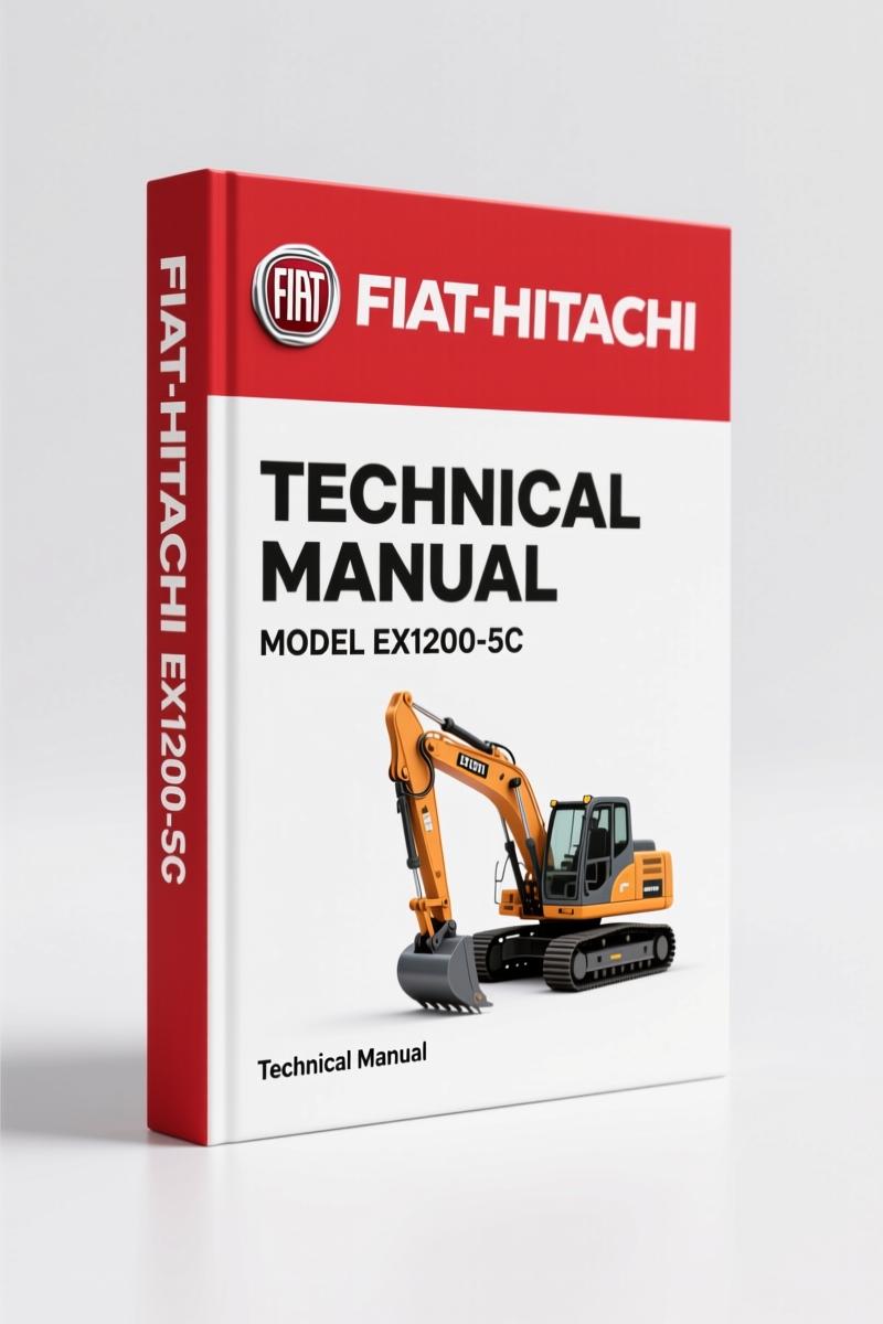
Fiat-hitachi EX1200-5C Technical Manual – 246-Page OEM Documentation
Original price was: $57.60.$40.00Current price is: $40.00.
246-page OEM technical manual for the Fiat-hitachi EX1200-5C excavator. Engine, hydraulic, and electrical system diagrams with factory tolerances.
Description
Fiat-hitachi EX1200-5C Technical Manual – No Substitutes
If you are pulling a pump or chasing a control issue on an EX1200-5C without the factory technical manual, you are burning billable hours and risking a comeback. Aftermarket manuals copy bits from older models and leave out critical info like the Fiat-hitachi EX1200-5C Technical Manual regulator adjustment sequence. I have seen a guy use a generic torque chart and snap a main relief valve stud. That repair cost more than this manual. This is the OEM document, straight from Hitachi’s engineering group. 246 pages of operational principle data – no shortcuts, no guesswork.
EX1200-5C Technical Manual: 246 Pages of Factory Data
Page 1 of this manual shows the volume number KM-18EE and confirms it is part of a three-volume set: Operational Principle, Troubleshooting, and Workshop. That matters because you can’t troubleshoot a pump control without understanding how it is supposed to work first. This volume gives you that foundation. Page 2 explains the safety alert symbol and the CAUTION headline – read that before you drop the upper structure. Most guys skip that page and end up with a crushed finger.
The manual is organized into three major sections: General, System, and Component Operation. Section 1, Group 1 covers specifications – engine data, working ranges for backhoe and loading shovel, hydraulic device specs, and electrical equipment ratings. You want the charge pressure? It is in there. Need the swing motor displacement? Listed under hydraulic devices.
Specifications and Component Layout
Group 2 of Section 1 lays out the component layouts – main components, electrical system components across four pages, pump area, and other subassemblies. The electrical system component diagrams show the location of every relay and fuse block. I have seen guys spend two hours tracing a no-start because they didn’t know where the bulb check relay was. The manual shows it in the layout on page 37 – or whatever page that group falls on. The point is, the layout is drawn to factory accuracy, not artist’s impression.
Engine Control and Pump Control Procedures
Section 2, System, starts with the control system. Group 1 goes through engine control, pump control, valve control, oil cooler fan motor control, and auto-lubrication control. If your EX1200-5C is idling up without a load, the engine control chapter explains the governor linkage and the feedback sensor. The pump control section covers the regulator logic – how the pump changes displacement based on pilot pressure. If you skip that, you will never set the horsepower correctly.
Group 2 covers the hydraulic system – pilot circuit, main circuit, pump transmission oil cooling circuit, and the oil cooler fan motor circuit. The main circuit schematic shows the flow combiner valve and the overload relief valves. Page numbers vary by edition, but the diagrams are indexed in the table of contents. Use that, not the online postage stamp images.
How the Electrical System is Documented
Group 3 of Section 2 is the electrical system. It starts with the power source circuit, then the bulb check circuit, engine start circuit, charging circuit (key switch on), accessory circuit, and surge voltage prevention circuit. The Electrical section is not just a wiring diagram – it describes the logic, like which relays close during engine cranking and how the surge suppressor protects the controller. If you are replacing a solenoid and the new one keeps welding, the surge prevention circuit is where you need to look.
Follow the Safety Alert Symbols – They Mean Something
Page 2 spells out the safety alert symbol and the headline notations. CAUTION means a potentially hazardous situation that could result in death or injury if not avoided. That is not boilerplate. When the manual says to use a lifting device for a component over 50 pounds, do it. The component operation section has weights listed for the swing motor and the travel reduction gear. Lifting those by hand is a fool’s game. Also, note the manual’s warning about using appropriate lifting techniques – they mean it.
Hydraulic System: Pilot, Main, and Cooling Circuits
Section 3, Component Operation, takes each device apart on paper. Group 1 covers the main pump and the oil cooler fan motor drive pump, the regulators, and the 3-unit pump. The regulator chapter explains the feedback spool and the torque limiter. Group 2 covers the swing device – swing motor, valve unit, parking brake, and reduction gear. The parking brake on this machine is spring-applied, hydraulically released. If you lose pilot pressure, the brake sets. The manual shows how to test the shuttle valve that feeds the brake release.
Group 3 dives into the control valve – flow combiner valve, main relief, overload relief, make-up valve, holding valve, arm regenerative valve, and boom overload relief pressure switch valve. That is seven valves in one stack. Each has a cross-section and a functional description. You cannot diagnose a drift in the boom without understanding the holding valve pilot port. The manual gives you that.
Groups 4 through 8 cover the pilot valve, travel device, signal control valve, upperstructure components (pilot shut-off, shockless valve, solenoid valve, oil cooler fan motor, accumulator, auto-lubrication), and undercarriage (swing bearing, center joint, track adjuster). The travel motor displacement angle change section in Group 5 is critical for high-speed travel troubleshooting.
If you need similar documentation for other models, check the Fiat-hitachi ZX800 Technical Manual – OEM Factory Specs for the compact line, or the Fiat-Hitachi 40U-2 50U-2 Technical Manual – 349 Pages OEM for smaller excavators. For the older EX series, the Fiat-hitachi EX135 1998 Technical Manual – OEM Function Description covers the predecessor. For background on how off-highway equipment transmissions differ from automotive, read the Manual Transmission overview. And if you are wondering about the difference between a wet clutch and a dry clutch, the Manual Transmission article explains the basics.
Frequently Asked Questions
- Does this manual cover troubleshooting?
- No. This is the Technical Manual (Operational Principle). Troubleshooting is a separate volume (TT18EE).
- What safety information is included in the manual?
- Page 2 of the manual defines the safety alert symbol and the CAUTION signal word. It states that CAUTION indicates a potentially hazardous situation which could, if not avoided, result in personal injury or death. The manual also includes component weights throughout and specifies when lifting equipment is required. For example, the swing motor is heavy enough that you need a hoist, not a back. Every section that involves handling heavy parts repeats the warning. The manual is consistent: if it says lift with a device, do it. I have seen a guy try to bench-press a travel motor and end up in the ER. The manual also notes that the safety alert symbol is used to draw attention to component/part weights. That is not optional.
Do not let the next job turn into a parts-ordering nightmare because you used a generic pin-crimp chart or guessed at the pilot pressure setting. Access the Factory Manual and have the actual OEM data on your screen or in your hand. Your time, your wallet, and your knuckles will thank you.
Additional information
| Brand | Fiat-hitachi |
|---|---|
| Language | English |
4 reviews for Fiat-hitachi EX1200-5C Technical Manual – 246-Page OEM Documentation
You may also like…
-
Sale!
Fiat-hitachi ZAXIS 200-3, 210H-3, 210K-3, 210N-3, 240-3 2006 Troubleshooting Manual
Original price was: $85.80.$65.00Current price is: $65.00. -
Sale!
Fiat-hitachi ZAXIS 650LC-3, 670LCH-3 2006 Troubleshooting Manual – 586 Pages
Original price was: $82.55.$65.00Current price is: $65.00. -
Sale!
Fiat-hitachi ZAXIS 330-3 2006 Troubleshooting Manual – 633 Pages
Original price was: $103.35.$65.00Current price is: $65.00. -
Sale!
Fiat-hitachi 850-3 2006 Troubleshooting Manual – 588 Pages OEM
Original price was: $91.00.$65.00Current price is: $65.00.
Related products
-
Sale!

1993 Operators Manual – International Bus 1000-3000 OEM Specs
Original price was: $12.30.$7.99Current price is: $7.99. -
Sale!

2006 Service Manual – International DT 466E, 530E Diesel Engine
Original price was: $67.50.$50.00Current price is: $50.00. -
Sale!

Technical Manual – International 6.0L Power Stroke FICM Diagnostics
Original price was: $29.80.$20.00Current price is: $20.00. -
Sale!
1995 Operators Manual – International 1000-4000 Series | OEM Documentation
Original price was: $12.49.$9.99Current price is: $9.99.
Michael T. –
Five stars! Quick access after payment. Contains clear wiring diagrams for Fiat-hitachi. Saved my repair job! Thank you.
John S. –
I am so happy with this purchase. Immediate link after checkout process. It guided me to repair my Fiat-hitachi EX12005C engine. Saved my weekend project! Thanks.
diy_master –
Perfect OEM spec sheet. The file looks clean. A must-have for any Fiat-hitachi EX12005C mechanic doing repairs. Saves me hundreds of dollars.
workshop_guy –
This is just what I was looking for. The PDF looks clean. It helped me to repair my Fiat-hitachi EX12005C engine. I will recommend this shop to others.