
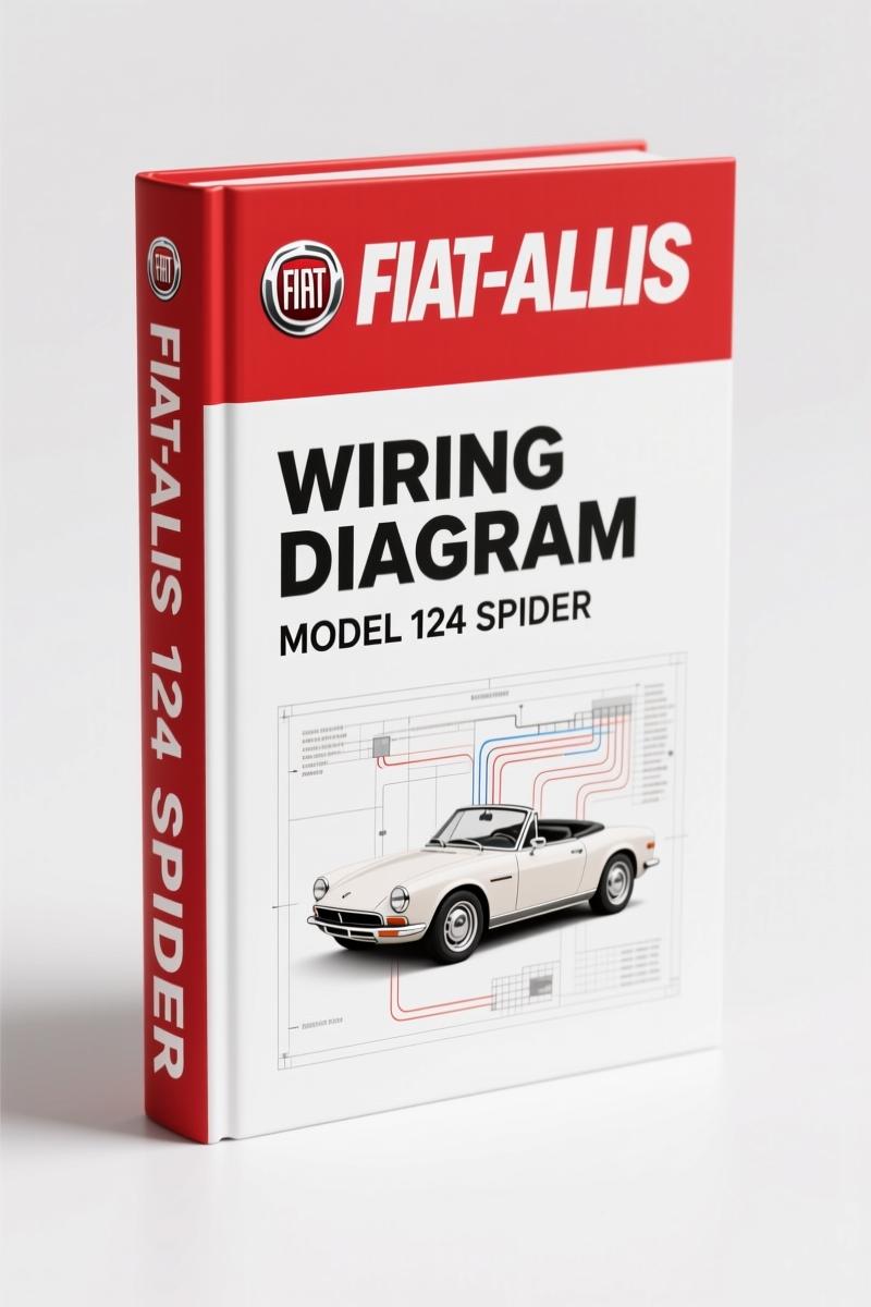
Fiat-allis 124 Spider 1980 Wiring Diagram – OEM Factory Specs
Original price was: $24.00.$20.00Current price is: $20.00.
Factory 1980 Fiat-allis 124 Spider wiring diagram. 14 pages of OEM circuits for ignition, cooling, fuel injection, and more.
Description
Fiat-allis 124 Spider 1980 Wiring Diagram – Original Factory Schematic
I’ve seen more than a few backyard jobs go sideways because some hack used a non-factory diagram and guessed the wire colors. The result? Fried alternators, melted harnesses, and a car that won’t start. This Fiat-allis 124 Spider 1980 Wiring Diagram is the real deal – a 14-page OEM document straight from the factory. No reprints, no third-party redraws. You get the exact wire colors, connector pinouts, and circuit paths that came off the assembly line.
Ignition and Starter Circuits – Page 1
Need to track down a no-crank condition or a faulty starter relay? Page 1 covers the ignition, starter, alternator, engine cooling fan, idle shutoff solenoid, and power distribution circuits. The factory schematic shows every wire color – black, violet, light blue, pink – with solid lines for power and dashed for ground paths. The note at the bottom is critical: on carbureted cars, the wire from the fuse box to connector C24 is light blue/black instead of the fuel-injection version. That kind of detail is exactly why you don’t trust aftermarket diagrams.
Cooling Fan and Idle Shutoff Solenoid Circuits
The engine cooling fan thermo-switch (01121) and the gulp valve electrovalve (65306) are drawn with their connector codes – G1, C17, C22. If your Spider’s electric fan doesn’t kick on, you need to verify continuity through the thermo-switch and the fuse box. This diagram tells you exactly which pins to check. For the idle shutoff solenoid (05100), note that it’s only present on carbureted models. The in-line fuse (04501) protects that circuit – don’t overlook it. Refer to the automotive wiring basics if you’re new to reading these schematics.
What the 14 Pages Cover
This wiring diagram is not a full service manual – it’s a focused electrical guide. Here’s what each page covers from the table of contents:
- Page 1: Ignition, starter, alternator, cooling fan, idle shutoff solenoid, power distribution
- Page 2: Starter circuit – automatic transmission
- Page 3: High and low beam circuits
- Page 4: Parking, license plate, side marker, panel lights
- Page 5: Hazard, turn signal, back-up, stop lights
- Page 6: Instruments, indicators, seat belt warning, courtesy light, clock, socket
- Page 7: Windshield wiper/washer, heater, horn, cigarette lighter
- Page 8: Power windows and radio
- Pages 9/10: Fuel injection system circuits
- Page 11: Component index
- Page 12: Connector codes (e.g., C2, C17, C31, G1)
- Page 13: Component board layout
That’s every electrical system in the car – including the transmission starter interlock, engine cooling fan relay, and the fuel injection harness. For the 124 Spider, the 1980 model year had both carbureted and Fuel Injection (Spider 2000) versions; the OCR excerpt on page 1 specifically distinguishes between them.
3 Reasons Aftermarket Wiring Diagrams Fail
First, aftermarket diagrams often blur wire colors – they’ll say “red/blue” when the factory uses “gray/red” (as seen in the high/low beam circuit on page 3). Second, they skip connector codes like C5, C7, C18 that are essential for tracing a circuit through the harness. Third, they don’t include the factory notes – like the one that warns the idle shutoff solenoid is only on carbureted cars. This OEM document eliminates all that guesswork. Pair it with the Fiat-allis Scudo 2006 Training Manual – OEM Factory Specs”>Scudo training manual if you’re working on multiple generations of Fiat-allis vehicles.
Verify the Connector Codes Before You Start
Look at the starter circuit for automatic transmission (page 2). You’ll see connectors C5, C7, C18, C31, C45, and C37. Each has a specific pinout – the gear selector light (02116) gets a white wire from C18, while the starter relay (00601) uses red, gray/black, and red. If your multimeter shows an open at C18, you know the back-up light switch is likely bad. This is the level of diagnostic precision you get when you use factory documentation. For more on interpreting these diagrams, read the Automotive Wiring”>automotive wiring guides on connector identification.
Fuel Injection System Circuits: Factory Routing
Pages 9 and 10 are dedicated to the fuel injection system. The relay set (00649) and the breakerless distributor (02601) are shown with their exact wire paths. The ignition coil (05703) is wired through a brown wire to the tachometer (02400). If you’re swapping a carbureted engine to fuel injection or vice versa, this diagram shows the harness differences – note the in-line fuse location and the idle shutoff solenoid omission. The component index on page 11 gives part numbers for every switch, relay, and motor referenced in the diagram.
- Does this wiring diagram cover the automatic transmission starter circuit?
- Yes. Circuit 2 on page 2 specifically covers the starter circuit for automatic transmission models, including the seat belt buzzer relay and gear selector light.
- What’s the difference between carbureted and fuel injection wiring in this diagram?
- The factory note on page 1 is explicit: on carbureted vehicles, the wire from the fuse box to connector C24 is light blue/black, and the idle shutoff solenoid (05100) and gulp valve electrovalve (65306) are present. On fuel injection cars (Spider 2000), those components are absent, and the relay set (00649) takes over. The cooling fan thermo-switch and alternator circuits are identical, but the distributor uses a breakerless trigger on fuel injection cars. If you’re working on an early 1980 model with a carburetor, use the light blue/black wire routing; if it’s a later fuel-injected Spider 2000, follow the diagrams on pages 9/10 for the injection harness. The connector codes remain the same, but pin assignments differ – always cross-reference the component board on page 13 to verify your harness year.
This is the wiring diagram that should have been under the seat of every 124 Spider from the factory. It’s clean, accurate, and complete. If you’re restoring or repairing a 1980 Fiat-allis 124 Spider, stop chasing ghosts with a generic diagram. Get the factory original. Access the Factory Manual.
Check out these related manuals: Fiat-Allis FL20 Operators Manual – Crawler Loader Operation and Maintenance”>FL20 operator’s manual and Fiat-allis Bravo, Brava 2000 Workshop Manual – 11,181 Pages”>Bravo/Brava workshop manual.
Additional information
| Brand | Fiat-allis |
|---|---|
| Language | English |
3 reviews for Fiat-allis 124 Spider 1980 Wiring Diagram – OEM Factory Specs
You may also like…
-
Sale!
Fiat-allis 460 Parts Catalog – 235 Pages OEM Part Identification
Original price was: $69.75.$45.00Current price is: $45.00. -
Sale!
Fiat-allis 745-B Parts Catalog – 327 Pages of OEM Part Specs
Original price was: $54.00.$45.00Current price is: $45.00. -
Sale!
Fiat-allis FG75, FG85, FG95 Technical Manual – 479 Pages OEM Specs
Original price was: $70.65.$45.00Current price is: $45.00. -
Sale!
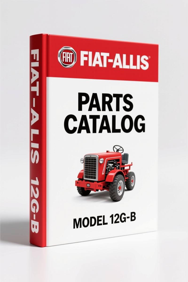
Fiat-allis 12G-B 1979 Parts Catalog – OEM Parts & Exploded Views
Original price was: $86.45.$65.00Current price is: $65.00.
Related products
-
Sale!

1993 Electrical Schematic – International 1000/3000/4000 Bus Chassis OEM Wiring Diagrams
Original price was: $29.26.$22.00Current price is: $22.00. -
Sale!
1992 Electrical Schematic – International 1000/3000/4000/2554 OEM Wiring Diagrams (132 Pages)
Original price was: $26.40.$20.00Current price is: $20.00. -
Sale!

Technical Manual – International DT 530 & HT 530 (118 Pages)
Original price was: $37.00.$25.00Current price is: $25.00. -
Sale!

Service Manual – International HS 2.8L Engine – 130 Pages of Factory Specs
Original price was: $56.40.$40.00Current price is: $40.00.
Richard G. –
Superb resource! The text is searchable and well indexed. A must-have for any Fiat-allis 124 DIYer doing repairs. I will recommend this shop to others.
Thomas B. –
Outstanding! The PDF looks clean. Every torque spec is provided for Fiat-allis 124. Saved my repair job! Thank you.
diy_master –
This is just what I required. Quick access after checkout. A must-have for any Fiat-allis 124 DIYer doing repairs. Saved my weekend project! Thank you.