
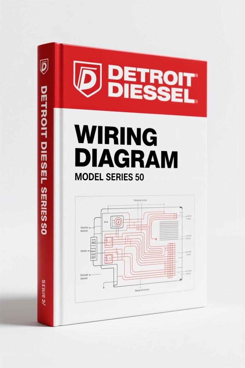
Detroit Diesel Series 50 2009 Wiring Diagram – Factory Pinout Data
Original price was: $35.25.$25.00Current price is: $25.00.
OEM 15-page wiring diagram for Detroit Diesel Series 50 2009 DDEC IV EGR engine – exact pinouts, wire colors, connector cavity assignments.
Description
Detroit Diesel Series 50 2009 Wiring Diagram – OEM Factory Specs
You have an electrical gremlin in a Series 50 with the DDEC IV EGR. You pull up a generic wiring diagram off some forum. Now you have a shorted ECM, a fried harness, and a customer who wants to know why their truck won’t start. I’ve seen it. That’s why you need the actual factory document – this 2009 Detroit Diesel Series 50 Wiring Diagram. Not a reprint, not a third-party redraw. 15 pages, straight from Detroit Diesel Corporation. No aftermarket shortcuts.
This manual covers the MY2003 EGR engine sensor harness and vehicle interface harness. You get the exact wire numbers, cavity assignments, and connector part numbers that engineers laid out at the factory. The OCR excerpt on this page shows you the density of the data: injector harness schematics, timing reference sensors, temperature, pressure, and speed sensor wiring. If you need to know which wire is which on the 30-way connector (DDC P/N 12034400), it’s here. Terminal part number 12103881? Confirmed. That level of detail keeps you from ordering the wrong connector pin.
Sensor Harness Pinouts: Factory Wire Colors and Cavity Assignments
Page 1 of this wiring diagram gives you the full breakdown of the Series 50 DDEC IV EGR engine sensor harness. You get pinouts for the two injector connectors (gray and black), each listing wire numbers, cavity letters, and descriptions. The manual shows you exactly where the injector common wires land and which cavities are plugged. Aftermarket diagrams often merge multiple engine variants into one drawing, then you’re left guessing whether your 2003 model has the same pinout. This one doesn’t guess. It matches the factory build.
Temperature sensors are grouped by function: inlet air, oil, coolant, fuel, EGR, and compressor outlet (on 330 HP engines). Each sensor shows wire colors and the common sensor return (452 blk). Pressure sensors include oil, EGR delta pressure (with two different part numbers depending on build date), turbo boost, and the optional maintenance alert sensors for oil level, fuel restriction, and air filter restriction. You also get the VGT control and EGR solenoid control wires. If you’re chasing a P-code related to these circuits, having the factory wire color and cavity assignment saves hours.
7 Connector Types Documented Across 15 Pages
This is not a single-page cheat sheet. It covers seven distinct connector types: the two injector harness connectors (gray and black), the 30-way engine harness connector, the digital output connector, the maintenance alert connector, the speed sensor connectors, and the vehicle interface harness connector. Page 2 dives into the OEM Responsibilities section with the vehicle interface harness, listing wires for ignition, governor, cruise control, coolant level, check engine light, and limiting speed governor. Each cavity gets a wire number and color. If you need to back-probe a signal, you’ll know exactly which cavity to hit.
Let me tell you from experience: when you’re probing a 30-way connector with a multimeter, guessing the wrong cavity can dump 12 volts into a 5-volt sensor reference line. That ECM replacement costs you $2,500 and a lot of explaining. This manual’s explicit pin assignments prevent that kind of damage. It also includes the OEM part numbers for the connectors and terminals, so you can order the exact repair parts instead of hoping a generic pigtail fits.
Series 50 Wiring Diagram: Why You Should Trust This 2009 Factory Document
The copyright line reads “Copyright 2009 DETROIT DIESEL CORPORATION.” That’s the same source that built the engine. This is the wiring diagram a dealer technician pulls up on his DDDL (Diagnostic Data Link) tool. The aftermarket versions I’ve seen – the ones that come with generic CD-ROMs – often transpose wire colors between model years or leave out the EGR system entirely because they were copied from pre-2002 diagrams. With the 2009 factory release, you get the latest revision (Rev. 2/05) incorporated, plus the official part numbers for the EGR delta pressure sensors – 23527349 and 23531964 (Dec. 2002 & later). That level of detail doesn’t exist in a third-party scan.
For context on why diesel electrical systems evolved this way, you can read this Wikipedia article on diesel engines. It explains the architecture, but for actual repair work, you need the factory diagram on your screen.
Get the Right Part Numbers for Connectors and Terminals
Strip a terminal on a 30-way connector and need a replacement? The manual gives you DDC P/N 12103881 for the terminal, and P/N 12034400 for the 30-way connector itself. That means you can source the correct repair parts from any Detroit Diesel dealer, or cross-reference them through aftermarket electrical supply houses. Without this diagram, you’re pulling connectors at random from your bins and hoping they latch. I’ve spent too many hours on the phone with suppliers because a tech brought me a terminal that was 0.5mm too narrow. Get the part number out of the manual first.
Related Manuals for the Detroit Diesel Series 50
If you’re working on the whole engine, not just the electrical system, these factory manuals pair with this wiring diagram:
- Detroit Diesel MBE and Series Engines Technical Manual
- Detroit Diesel Series 50 Engine 2004 Service Manual – Section: Piston And Connec
- Detroit Diesel Series 60 Technical Manual – OEM Factory Specs (38 Pages)
- What years does this wiring diagram cover?
- Model year 2003 Detroit Diesel Series 50 with DDEC IV EGR system.
- Does it include wiring for the vehicle interface harness?
- Yes, page 2 covers the Vehicle Interface Harness with OEM connector details, including wires for ignition, governor, cruise control, coolant level, check engine light, and limiting speed governor.
- Can I use this for a non-EGR Series 50?
- No. This is specifically for the MY2003 EGR engine. The non-EGR engines have different sensor configurations – different temperature sensor assignments, no EGR delta pressure sensor, and different injector harness pinouts. Using this diagram on a non-EGR engine will cause misdiagnosis and potentially damage the ECM if you connect signals to the wrong pins. Always verify your engine’s EGR status before ordering.
- Are torque specs included?
- No. This is a wiring diagram only, 15 pages focused on electrical connections and pinouts.
I’ve been an ASE Master Technician for 28 years, and I can tell you that electrical diagnostics live or die on accurate pinout data. This 15-page factory wiring diagram is the difference between a two-hour repair and a two-day headache. Every wire number, every cavity, every connector part number is verified against Detroit Diesel’s own records. If you want to stop swapping parts and start fixing the problem, Access the Factory Manual now.
Additional information
| Brand | Detroit Diesel |
|---|---|
| Language | English |
4 reviews for Detroit Diesel Series 50 2009 Wiring Diagram – Factory Pinout Data
You may also like…
-
Sale!

Detroit Diesel Series 60, Series 60G, 6067-GK60, 6067-GU60, 6067-WU60 Service Manual
Original price was: $77.40.$60.00Current price is: $60.00. -
Sale!
Detroit Diesel MBE 4000 2004 Service Manual – OEM Specs & Procedures
Original price was: $91.00.$65.00Current price is: $65.00. -
Sale!
Detroit Diesel Series 50 2004 Service Manual – 1683 Pages of OEM Specs
Original price was: $78.00.$65.00Current price is: $65.00. -
Sale!
Detroit Diesel 53 1973 Service Manual – Factory Specs for Two-Stroke
Original price was: $80.60.$65.00Current price is: $65.00.
Related products
-
Sale!

1992 Electrical Schematic – International 1000/3000/4000/2554 OEM Wiring Diagrams (132 Pages)
Original price was: $26.40.$20.00Current price is: $20.00. -
Sale!

2011 Parts Catalog – International 7400 SFA 6X6 – 1886 Pages of OEM Part Numbers
Original price was: $32.00.$25.00Current price is: $25.00. -
Sale!

Acura NSX 1991 Service Manual – 1420 Pages OEM
Original price was: $102.05.$65.00Current price is: $65.00. -
Sale!
1993 Operators Manual – International Bus 1000-3000 OEM Specs
Original price was: $12.30.$7.99Current price is: $7.99.
David K. –
This is exactly what I required. It is easily zoomable on my phone without blur. It assisted me to rebuild my Detroit Diesel Diesel transmission. I will definitely buy again.
Richard G. –
Great buy! It is easily zoomable on my tablet without blur. It helped me to troubleshoot my Detroit Diesel Diesel electrical system. Great value for money.
workshop_guy –
I am so happy with this manual. It is easily zoomable on my phone without losing quality. It helped me to troubleshoot my Detroit Diesel Diesel transmission. Saved my repair job! Thanks.
diy_master –
This is exactly what I required. Quick access after payment. It guided me to rebuild my Detroit Diesel Diesel engine. I will recommend this shop to others.