
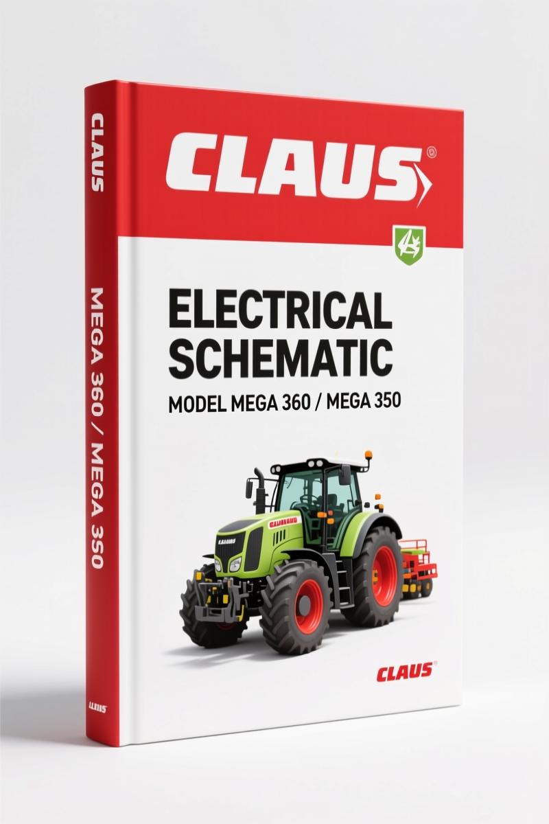
Claas MEGA 360 MEGA 350 Electrical Schematic – Factory Wiring Diagrams
Original price was: $28.60.$20.00Current price is: $20.00.
OEM electrical schematic for Claas MEGA 360/350 combines. 220 pages, circuit diagrams, module pin assignments, and central terminal compartment wiring.
Description
Claas MEGA 360, MEGA 350 Electrical Schematic – Factory Diagrams That Don’t Waste Your Time
I’ve seen more fried modules and melted harnesses from guys using aftermarket wiring sketches than from any actual mechanical failure. You can’t trace a short on a combine with a photocopied diagram that’s been faxed three times. That’s why you need the real thing – the factory Claas MEGA 360, MEGA 350 Electrical Schematic. 220 pages of OEM wiring, not some re-drawn version that hides the hard stuff. If you’re chasing a no-start on the diesel engine or trying to figure out why the AUTOPILOT won’t engage, this is the only document you should trust.
Electrical Schematic Breakdown: 40+ Circuit Diagrams
You get a full set of individual circuit diagrams numbered from 1a to 40a. That’s not marketing fluff – every one of those diagrams covers a specific function: main power supply, diesel engine electric starting motor (1a), diesel engine cut-off system (3a), threshing mechanism circuits with serial number splits (7a/7b), fan variable-speed drive (10a), grain tank unloading (15a), front attachment drive and reverser drive (17a/17b/17c), reel variable-speed (19a), AUTOCONTOUR (24a), CONTOUR (24b), speed monitoring (25a), machine monitoring (26a/26b), yield meter (27a), AUTOPILOT (28a), all-wheel drive (29a), lighting circuits (32a-35a), air conditioner (38a/38b), and a dozen more. The table of contents calls them out exactly. You won’t waste time flipping through generic pages.
Pin Assignments and Module Diagrams
Every module pinout is documented with spare part numbers. The automatic air conditioner module A6, cab fan speed controller module A7, AUTOCONTOUR module A8 (spare part no. 011 015.x), Contour module A8 (spare part no. 011 026.x), AUTOPILOT module A9, speed monitor module A12, electronic engine control module A15, engine adaptation module A17, yield meter module A21, deflector adjustment module A26 – they’re all in there. You get connector tables with wire colors and cross-sections in mm². For example, the connections list shows from HKB-17 to K77/86 using 0.75 mm² brown wire, and KBA-10 to Y25 using 0.5 mm² black wire. That’s the level of detail you need when you’re probing a harness.
Which Circuits Are Covered?
Everything electrical on the MEGA 360 and MEGA 350. The manual separates circuits by serial number breaks – critical for the threshing mechanism (up to 835 00146 / 845 00123 and from 835 00147 / 845 00124), work lights, machine monitoring, and front attachment drive. You also get the central terminal compartment layout (ZE-2) and component grid coordinates so you can find any relay, fuse, or module physically on the machine. The index covers designations A through Y – terminals, modules, sensors, lighting, fuses, voltage sources, signaling devices, relays, motors, gauges, potentiometers, switches, connectors, solenoid coils. If it has a wire, it’s in here.
3 Serial Number Splits You Must Check
First: threshing mechanism circuit – diagrams 7a and 7b depend on whether your machine is above or below serial numbers 835 00146 / 845 00123. Second: front attachment drive and reverser drive (hydraulic) – diagrams 17b vs 17c split at the same break. Third: machine monitoring and work lights – diagrams 26a/26b and 34a/34b. Mix those up and you’ll be tracing a ghost circuit. This manual calls out each split explicitly, so you won’t guess.
Read the Layout Before You Probe Anything
Start with the layout of electric circuit diagrams on page 3. It explains how the circuit numbering works, the potential designations (main battery, ignition-switched, relay-controlled, ground), and the connection identifiers. The manual shows you that many circuits depend on the road travel activation switch S52 (see circuit diagram 04a) – so if you’re troubleshooting circuits 20, 24, or 30 and they won’t activate, check S52 first. That’s the kind of factory logic you don’t get from a generic wiring book. And for God’s sake, disconnect the battery before you start poking around – the manual warns about that too.
Source Authenticity: OEM vs Aftermarket
This is a genuine Claas factory document, not a third-party reprint. The file name says it all: CLAAS_MEGA_360-MEGA_350_Electrical_Schematic_en-20424014165.pdf. The pin assignments reference Claas standards catalogue designations. The wire color codes follow Claas conventions (rd=red, bk=black, br=brown, wh=white, bl=blue, etc.). When you buy aftermarket diagrams, half the time the wire colors are wrong or the module pins don’t match. I’ve wasted billable hours on that junk. This manual is the only one I’d let my junior techs touch.
Related manuals you might need for your Claas equipment: Claas JAGUAR 900 2002 Training Manual – Factory Specs for Speedstar”>Claas JAGUAR 900 2002 Training Manual – Factory Specs for Speedstar, CLAAS LEXION 500 Series Operators Manual CEBIS”>CLAAS LEXION 500 Series Operators Manual CEBIS, and Claas Dominator 68 S Operator’s Manual”>Claas Dominator 68 S Operator’s Manual. For a broader understanding of wiring principles, check out Automotive Wiring”>Automotive Wiring and the Automotive Industry Overview.
Frequently Asked Questions
- Is this manual for both MEGA 360 and MEGA 350?
- Yes – the cover says MEGA 360 – 350, and the contents apply to both models.
- Does it include the engine control module pinout?
- Yes, module A15 (Electronic engine control module) and A17 (Engine adaptation module) have full pin assignments with wire colors and connector locations. You’ll find them in the “Pin assignment in modules” section starting around page ZE-6.
- Are there diagrams for the air conditioner?
- Absolutely. Circuit diagrams 38a (compressor-type air conditioner, cab fan) and 38b (automatic air conditioner) cover both HVAC systems. The automatic air conditioner module A6 pinout is also included separately. Each diagram shows the compressor clutch circuit, fan speeds, and control wiring. If your cab won’t cool, start at diagram 38a and check power at the compressor relay.
- Why are there serial number splits in the diagrams?
- Claas updated wiring harnesses during production for the threshing mechanism, front attachment drive, work lights, and machine monitoring. The manual provides separate diagrams for machines up to serial number 835 00146 / 845 00123 and from serial number 835 00147 / 845 00124. Ignoring the split means you’ll use the wrong diagram.
Stop burning through harnesses and chasing down wrong wires. Access the Factory Manual – it’s the only electrical schematic you should trust for your Claas MEGA 360 or MEGA 350.
Additional information
| Brand | Claas |
|---|---|
| Language | English |
2 reviews for Claas MEGA 360 MEGA 350 Electrical Schematic – Factory Wiring Diagrams
You may also like…
-
Sale!

Claas AVERO 240, AVERO 160 2015 Repair Manual – Factory Specs
Original price was: $88.80.$60.00Current price is: $60.00. -
Sale!

Claas Quadrant 1200 1993 Repair Manual – Factory OEM Specs
Original price was: $101.50.$70.00Current price is: $70.00. -
Sale!
Claas DOMINATOR 108 VX & 88 VX Service Manual – 1044 Pages
Original price was: $59.85.$45.00Current price is: $45.00. -
Sale!

Claas QUADRANT 2200, QUADRANT 2200 ROTO CUT Repair Manual – 433 Pages of Factory Specs
Original price was: $100.10.$65.00Current price is: $65.00.
Related products
-
Sale!

Technical Manual – International DT 530 & HT 530 (118 Pages)
Original price was: $37.00.$25.00Current price is: $25.00. -
Sale!

1993 Operators Manual – International Bus 1000-3000 OEM Specs
Original price was: $12.30.$7.99Current price is: $7.99. -
Sale!

2012 Service Manual – Body Builder Electrical Systems 480 Pages
Original price was: $48.28.$34.00Current price is: $34.00. -
Sale!

2004 Acura TSX Wiring Diagram – 73-Page Factory Electrical Schematics
Original price was: $15.88.$9.99Current price is: $9.99.
pro_mechanic –
Great workshop guide. It is easily zoomable on my laptop without blur. Every spec sheet is provided for Claas MEGA. Saves me hundreds of money.
Michael T. –
Highly recommended! Immediate link after checkout. A must-have for any Claas MEGA DIYer doing repairs. Saves me a lot of time.