
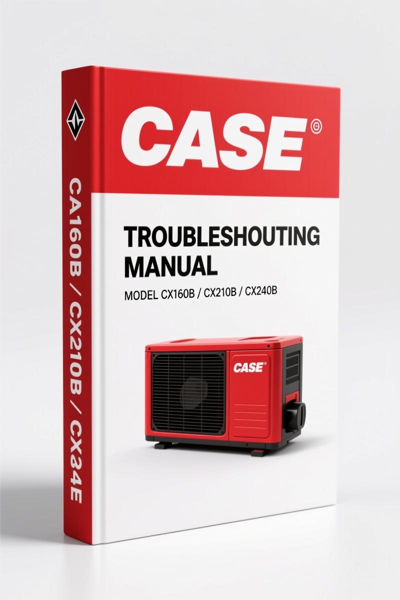
Case CX160B, CX180B, CX210B, CX290B, CX230B 2006 Electrical Schematic
Original price was: $39.75.$25.00Current price is: $25.00.
OEM electrical schematic for Case CX160B-CX290B excavators (2006). 114 pages of layout diagrams, component locations, and circuit explanations.
Description
Case CX160B, CX180B, CX210B, CX290B, CX230B 2006 Electrical Schematic – Factory Wiring Layout Diagrams
Case CX160B, CX180B, CX210B, CX290B, CX230B 2006 Electrical Schematic – if you’ve ever chased a short on a CX-series excavator using a generic wiring diagram, you know the headache. Wrong pinouts, missing relays, phantom grounds. This isn’t a third-party sketch. It’s the actual OEM layout diagram from Case’s Monthyon training centre, dated February 2006. 114 pages of exactly where every component lives – from the ECM in the cab to the electromagnetic fuel pump in the pump compartment. No guesswork. Just the factory positions and connections.
Electrical Equipment Layout Diagram – 7 Systems Covered
This manual organizes the electrical system into six layout sections plus an explanation of circuit operation. You get the Overall View showing how the main unit right side (radiator compartment), engine, main unit left side (pump compartment), center section, and cab fit together. From there each section breaks down by model: CX160B/CX180B, CX210B/CX230B/CX240B, and CX290B. Every component is numbered and labeled – the 5-way solenoid valve, P1 pressure sensor, travel speed solenoid, swing lock, N2 pressure sensor, oil temperature sensor. If you need to locate the horsepower control proportional valve on a CX290B, it’s in Section 3 with a clear callout.
What Torque Values Are Listed?
Because this is an electrical schematic, you won’t find head bolt torque data. What you do get is the factory-specified routing and connector positions that prevent you from damaging harnesses during teardown. Knowing exactly where the lever lock solenoid sits relative to the boosted pressure sensor saves you from crushing a wire when reinstalling the pump cover. The manual doesn’t include torque specs for electrical terminals – that’s covered in the corresponding service manual. But if you’re pairing this schematic with the CASE CX160B CX180B 2007 Service Manual, you’ll have the full picture.
Main Unit Left Side: Pump Compartment Components
Section 3 is where the real diagnostic work happens. The left-side layout diagram covers the pump compartment with 14 labeled items: electromagnetic fuel pump, P1 and P2 pressure sensors, 5-way solenoid valve, boosted pressure sensor, travel speed solenoid, swing lock, power save, lever lock, N1 and N2 pressure sensors, P1 flow control proportional valve, horsepower control proportional valve, and oil temperature sensor. Each component has a fixed position – no “typical location” nonsense. For a CX210B, CX230B, or CX240B, the layout is identical to the CX160B/CX180B except for minor wiring differences noted in the circuit explanation. The CX290B gets its own subsection. If you’re swapping a P1 pressure sensor on a CX290B, page 26 shows the exact mounting orientation so you don’t cross-thread the port.
Understand the Wiring Before You Touch It
This manual includes a dedicated 51_Explanation.pdf section titled “Electric circuits operation ex.” That’s where the factory describes how each circuit behaves – what voltage to expect at the controller, which relay feeds which fuse, and how the ECM interacts with the cab controls. Before you start probing wires, read that section. It saves you from backprobing the wrong pin on controller A and blowing a fuse. The cab layout diagrams (Section 5) show you the fuse box with F7 through F26, relays R1 through R11, and the exact position of the ECM. Non-factory wiring diagrams from aftermarket sources often mislabel the female pins on the ECM connector – this one doesn’t.
3 Reasons This OEM Schematic Beats Aftermarket Versions
First, orientation. The overall view on page 1 shows the machine from above with numbered callouts – you see exactly where the main unit right side ends and the engine begins. Second, model specificity. The manual separates CX160B/CX180B, CX210B/CX230B/CX240B, and CX290B into distinct columns, so you’re not hunting through generic pages. Third, the layout diagrams use actual part numbers and sensor names, not generic symbols. Aftermarket versions of the CX series electrical manual frequently omit the power save sensor location or mislabel the travel speed connector. That’s a safety risk when you’re working near the hydraulic lines under the cab. Stick with factory documentation. Automotive Wiring best practices start with having the correct OEM print on your tablet.
FAQ
- Does this manual cover the CX230B model?
- Yes. The CX230B is grouped with the CX210B and CX240B in the b) subsections. All three share layout diagrams for main unit right side, engine, left side, center section, and cab. The CX290B has its own c) subsection.
- Is there any hydraulic or mechanical information in this schematic?
- No. This is strictly electrical layout. For hydraulic circuit operation, see the CASE CX210B CX290B 2007 Hydraulic Training Manual.
- What page shows the controller A location?
- Controller A is in Cab Layout Diagram 1 (Section 5). The exact relay and fuse numbering – R1 through R11, F7 through F26 – is listed.
- Can I use this to diagnose a no-start condition on a CX160B?
- Absolutely. Start with the overall view to trace power from the main unit right side (radiator compartment) through the engine section to the cab. Then check the fuse box for F19 (ECM power) and relay R5 (fuel pump). If you need ECM pinouts, the 51_Explanation.pdf includes circuit operation details. For full diagnostics, pair it with the CASE CX210B CX290B 2007 Diagnostics Manual.
A CX-series excavator electrical system isn’t something you eyeball. One wrong connection on the 5-way solenoid valve can trigger a false swing brake code. One missed ground on the ECM can cause intermittent shutdown on a job site. This manual puts the factory layout in your hands – exactly how Case designed it. Access the Factory Manual and keep it on your workbench or tablet. You’ll trace circuits faster, replace sensors without guessing connector locations, and avoid the rework that comes from aftermarket errors. For more on the automotive industry as a whole, see Automotive Industry Overview.
- CASE CX160B CX180B 2007 Service Manual
- CASE CX210B CX290B 2007 Hydraulic Training Manual
- CASE CX210B CX290B 2007 Diagnostics Manual
Additional information
| Brand | Case |
|---|---|
| Language | English |
4 reviews for Case CX160B, CX180B, CX210B, CX290B, CX230B 2006 Electrical Schematic
You may also like…
-
Sale!

Case 50 Crawler Series D Service Manual – Factory Specs & Electrical
Original price was: $98.00.$70.00Current price is: $70.00. -
Sale!

Case 2500 Service Manual – OEM Factory Specs for Cruz-Crane
Original price was: $97.30.$70.00Current price is: $70.00. -
Sale!

Case 26, 26B, 26S 1975 Parts Catalog – Factory Exploded-View Parts Identification
Original price was: $114.00.$75.00Current price is: $75.00. -
Sale!

Case 34, 680 CK 1967 Parts Catalog – OEM Factory Parts
Original price was: $107.25.$75.00Current price is: $75.00.
Related products
-
Sale!

Service Manual – International HS 2.8L Engine – 130 Pages of Factory Specs
Original price was: $56.40.$40.00Current price is: $40.00. -
Sale!

International 1000-3000 Series Operators Manual – 132 Pages of OEM Specs
Original price was: $14.40.$10.99Current price is: $10.99. -
Sale!
1995 Operators Manual – International 1000-4000 Series | OEM Documentation
Original price was: $12.49.$9.99Current price is: $9.99. -
Sale!

Acura NSX 1991 Service Manual – 1420 Pages OEM
Original price was: $102.05.$65.00Current price is: $65.00.
William H. –
I am very pleased with this manual. The pages are clean and easy to navigate. Contains precise schematics for Case. Saves me hundreds of money.
gearhead88 –
This is just what I required. It is easily zoomable on my laptop without blur. Contains precise wiring diagrams for Case. I will definitely buy again.
James L. –
Highly recommended! It is very easy to read on my tablet without losing quality. Contains detailed wiring diagrams for Case. Saves me a lot of money.
diy_master –
Outstanding! Instant access after checkout. Contains precise schematics for Case. Worth every penny.