
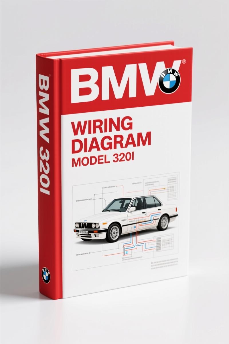
BMW 320i 1977 Wiring Diagram – OEM Factory Schematic
Original price was: $37.50.$25.00Current price is: $25.00.
OEM factory wiring diagram for 1977 BMW 320i. 15 pages of circuit index, ground bus, and component locations.
Description
BMW 320i 1977 Wiring Diagram – Factory OEM Wiring Schematics
If you’re working on a 1977 BMW 320i and the electrical system is giving you fits, you need the factory Wiring Diagram. Not a scanned copy from a third-party that someone re-indexed and lost half the wire colors. I’ve been turning wrenches since before this car was new, and I can tell you the difference between an OEM schematic and a reprint is the difference between finding a short in ten minutes or chasing ghosts all afternoon. This is the real deal: 15 pages, published in 1977 by BMW, covering every circuit from the charge system to the brake lights. Let me walk you through what’s inside.
BMW 320i 1977 Wiring Diagram – Circuit Index Breakdown
The first thing you’ll notice is a proper Circuit Index listing 31 separate circuits – from AIR CONDITIONING (factory and dealer installed) to WINDSHIELD WIPER/WASHER. Each one has a page reference. You want the Fuel Delivery circuit? That’s on page 4-3. Need the Brake light circuit? Page 4-11. The index is organized so you find exactly what you need without flipping through every page. This is not a generic wiring diagram that lumps everything into one blurry drawing. Each circuit has its own schematic page with component locations, terminal details, and wire color codes. I’ve seen guys print a whole 200-page manual just to find one circuit – this thing gets you in and out.
Fuel Delivery and Start Circuits: Page 4-3 Details
Page 4-3 is probably the page you’ll use most. It covers the Charge system (alternator, generator warning light), the Ignition System (distributor, ignitions coil, cold start injector valve, thermo-time switch), and the Start circuit (starter motor, battery, unloader relay, ignition switch, starter relay for automatic transmission). The schematic shows the start-run bus, the ballast resistor (0.9Ω), and the diagnostic connector pinouts. Wire sizes are .75mm unless otherwise marked – that’s printed right on the drawing. If you’re diagnosing a no-start condition, this page alone saves you hours. The component location table tells you exactly where the cold start injector valve lives: right side of the engine, coolant connection flange, top front.
Where Are the Ground Points and Connectors?
Grounds are a common failure point on these cars. The manual lists five ground points: G17 (main body ground, left side of battery mounting base), G18 (engine ground, forward of starter), G49 (below lower left instrument panel), G102 (rear parcel shelf, left side), and a main engine ground shown on the schematic. Connectors are mapped too – C20h (15-pin rectangular in the distribution/fuse box), C20f (4-pin rectangular), C39 (9-pin rectangular). If you’re testing continuity, you need to know which pin belongs to which circuit. This diagram gives you that. I’ve had technicians ask me why their multimeter reads open when they’re probing the wrong connector – this manual prevents that.
3 Reasons Factory Documentation Beats Aftermarket Reprints
First, wire colors are printed on the schematic – not guessed. Aftermarket reprints often convert colors to gray-scale or use different abbreviations. Second, the component location photographs show the actual components on the vehicle, not generic drawings. Third, the factory includes the diagnostic connector pinouts and fuse designations (page 4-13 lists every fuse). When you’re troubleshooting an intermittent brake light or a fuel pump relay that won’t click, you need the exact OEM spec. I’ve compared aftermarket versions that had the wrong pin numbering – cost a customer a $300 ECU because someone swapped the ground wire. Don’t be that guy.
Brake and Warning Light Circuits: What to Check First
The wiring diagram covers Brake lights, Hazard lights, Turn signals, and the Warning Buzzer system. The brake light circuit includes the brake fluid level switch, brake differential pressure switch, and hand brake switch. The schematic shows how the seatbelt warning timer interacts with the dash warning display. If your brake lights don’t work, start by checking the brake pedal switch (terminals and wire colors are listed). Then verify ground G49. I’ve seen the G49 ground corrode and take out the whole warning buzzer system. The factory diagram maps the power bus and ground bus details so you can isolate problems fast.
Understanding the Wiring Before You Touch It
Before you start splicing or probing, spend fifteen minutes with this manual. Understanding Automotive Wiring basics helps, but this factory diagram eliminates guesswork. For later models, check the BMW 3-Series E36 1995 Electrical Troubleshooting Manual or the BMW 3 Series E36 1996 Electrical Troubleshooting Manual or the BMW 3 Series E36 1994 Electrical Troubleshooting Manual. But for a 1977 320i, this is the only one you need. The Automotive Wiring standards have changed, but this car’s schematic is rock-solid if you follow it.
- Does this manual include torque specifications?
- No. This is a wiring diagram, not a service manual. It covers electrical circuits only.
- How do I identify the C20h connector?
- The C20h is a 15-pin rectangular connector located in the distribution/fuse box. The diagram on page 4-3 shows pin assignments with wire colors and sizes. You need to verify continuity with a multimeter, not just a test light. I’ve seen technicians misread the pin numbering because they assumed orientation; the manual includes a component location photograph and terminal detail. Match your harness to the schematic before cutting any wires. The fuse box cover often has a diagram, but it can fade – this manual is your backup. Check the diagnostic connector page for additional pinouts if you’re testing the engine control system.
Don’t waste time with copied diagrams that lose resolution. Get the real factory schematic and fix your 320i right the first time. Access the Factory Manual from AutoRepairManuals – it’s the same document the dealer techs used in 1977.
Additional information
| Brand | BMW |
|---|---|
| Language | English |
3 reviews for BMW 320i 1977 Wiring Diagram – OEM Factory Schematic
You may also like…
-
Sale!

BMW 735i, 735iL, 740i, 740iL, 750iL Service Manual – 987 Pages
Original price was: $102.05.$65.00Current price is: $65.00. -
Sale!

BMW 525i, 530i, 535i, 540i Service Manual 1989-1995 Factory Specs
Original price was: $96.00.$60.00Current price is: $60.00. -
Sale!

BMW M3, 323i, 325i, 325xi, 328i Service Manual – 1258 Pages
Original price was: $93.00.$60.00Current price is: $60.00. -
Sale!

BMW 525i, 530i, 535i, 540i Service Manual – 459 Pages Factory Specs
Original price was: $73.20.$60.00Current price is: $60.00.
Related products
-
Sale!

1995 Operators Manual – International 1000-4000 Series | OEM Documentation
Original price was: $12.49.$9.99Current price is: $9.99. -
Sale!

Technical Manual – International DT 530 & HT 530 (118 Pages)
Original price was: $37.00.$25.00Current price is: $25.00. -
Sale!

2011 Parts Catalog – International 7400 SFA 6X6 – 1886 Pages of OEM Part Numbers
Original price was: $32.00.$25.00Current price is: $25.00. -
Sale!

Service Manual – International HS 2.8L Engine – 130 Pages of Factory Specs
Original price was: $56.40.$40.00Current price is: $40.00.
Charles W. –
I am so happy with this transaction. Instant access after checkout. Every torque spec is provided for BMW 320i. Saved my weekend project! Thank you.
John S. –
Perfect workshop guide. The pages are clean and well indexed. A must-have for any BMW 320i DIYer doing maintenance. Saved my repair job! Thank you.
gearhead88 –
Perfect factory service manual. Immediate link after checkout. It guided me to fix my BMW 320i electrical system. Saves me so much time.