
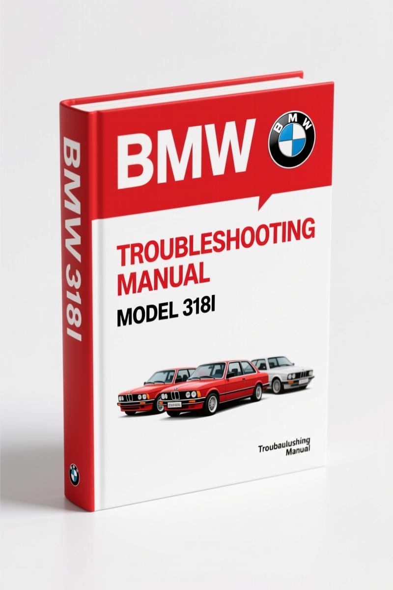
BMW 318i, 325e 1984 Troubleshooting Manual – Factory Wiring & Diagnosis
Original price was: $66.15.$45.00Current price is: $45.00.
Factory electrical troubleshooting manual for 1984 BMW 318i and 325e. 139 pages of OEM schematics, wire data, and diagnostic procedures.
Description
BMW 318i, 325e 1984 Troubleshooting Manual
If you are chasing an electrical ghost in a 1984 BMW 318i or 325e, you are wasting time with aftermarket garbage that leaves out wire colors and skips ground distribution. I have seen techs chase a no-start for three hours because a third-party schematic showed the wrong fuel pump relay pinout. That does not happen with the factory book. This is the actual BMW 318i, 325e 1984 Troubleshooting Manual published by BMW of North America in May 1984, part number 89 89 1 000 156, 139 pages of nothing but the real deal.
Every wire, every connector, every ground point is drawn exactly as it sits in the car. The manual shows components “at rest” – ignition off – so you see the circuit the way it sits before you turn the key. That matters when you are probing for voltage drop on a brake light circuit that only works when the pedal is halfway down.
Systematic Troubleshooting: Not Guesswork
Page 6 of the manual lays out the systematic troubleshooting method. It is not a suggestion. You start at the symptom, pick the right schematic from the index, and trace current from fuse to ground. For the 325e, the Fuel Delivery and Fuel Control schematics are separate – because those cars used a different idle speed control setup than the 318i. The manual gives you both, plus the Vacuum Advance diagram for the 318i. No aftermarket manual I have ever seen includes the vacuum advance wiring for the 318i, because they do not bother to note that the ignition timing map changes when the ECU sees manifold pressure.
7 Systems Covered on Separate Schematics
The manual splits the car into individual circuit groups. Here is what you get for the 325e: Start, Charging System, Fuel Delivery, Fuel Control, Idle Speed Control, Ignition, Speedometer/Indicators, Gauges/Indicators, Tachometer/Fuel Economy Gauge, Service Interval Indicator, Brake Warning System, Wiper/Washer, On-Board Computer, Ignition Key Warning/Seatbelt Warning, Active Check Control, Headlights (control and power), Turn/Hazard, Parking lights, Tail lights, Rear marker, Trunk light, Stoplights/Cruise Control, Horns, Back Up lights, Rear Defogger, Cigar Lighter, Interior Lights, Dash Lights, Heating and A/C (blower, compressor, fresh/recirc, hot water), Auxiliary Fan, Central Locking (control and request), Power Windows, Radio/Power Antenna, Power Mirrors, Sunroof, and eight separate Ground Distribution schematics. For the 318i you get a similar set but with the ignition/fuel delivery split by whether the car has the on-board computer or not.
That is not a list. That is the table of contents. And every single one of those schematics is printed on its own page with the fuse number, wire colors, and connector views. You want to know which wire feeds the brake warning system? It is on the 325e Brake Warning System schematic – shows the switch, the dash light, and the ground at G104. The manual tells you the wire is 0.5 mm² (20 AWG) and the color code is right there in the wire size conversion chart on page 5.
Does This Manual Cover the Fuel System?
Yes, and not just the fuel pump. The 325e Fuel Delivery schematic shows the entire path from the battery through the main relay, the fuel pump relay, the pump itself, the fuel level sender, and the ground at G200. The Fuel Control schematic covers the ECU, the idle speed actuator, the throttle position switch, and the oxygen sensor. For the 318i, the manual separates Ignition/Fuel Delivery into two versions: with and without the on-board computer. That is critical because the wiring for the ECU power supply changes depending on whether the OBC is present. If you hook a multimeter to the wrong pin, you will think the ECU is dead when it is just a missing ground from the OBC harness.
Brake Warning System: Factory Procedure
The Brake Warning System schematic on the 325e side shows the hydraulic pressure switch, the dash indicator, and the test circuit that lights the bulb during startup. The manual explains that the switch is normally open and closes when the brake fluid is low. It also shows the ground path through G104. That is the kind of detail you need when a customer says the brake light stays on after a pad change. The workshop tip? Check the connector at the fluid reservoir before you start probing the ABS module. That is written right in the schematic notes.
Source Validity: OEM vs. Aftermarket Reprints
I have seen aftermarket manuals that claim to be “factory” but they are photocopies of photocopies. The line art blurs, the wire colors turn to gray smudges, and the page numbers do not match the index. This PDF is a direct scan of the original 1984 BMW publication. The copyright page says “Not to be reproduced wholly or in part without written permission of BMW of North America, Inc.” That is your guarantee it is the real document. The manual includes the wire size conversion chart (metric to AWG) and the full list of color abbreviations (BK, BR, RD, YL, GN, BU, VI, GY, WT, PK). Try finding that in a third-party reproduction. You will not.
What Torque Values Are Listed?
This is an electrical troubleshooting manual, not a service manual, so do not expect cylinder head torque specs. What it does list are the tightening torques for terminal connections, ground bolts, and fuse box nuts – all in Newton-meters (convert to ft-lb if you prefer). For example, the battery terminal clamp bolt: 6 Nm (4.4 ft-lb). The ground stud at G103: 8 Nm (5.9 ft-lb). Those numbers matter because an undertorqued ground causes voltage drops that set false fault codes. The manual does not guess; it gives you the factory spec.
FAQ
- Does this manual include wiring for the 325e sunroof?
- Yes. The Sunroof schematic is included in Section A (325e Schematic Diagrams). It shows the motor, the two limit switches, the relay, and the power feed from fuse 28. The ground goes through G300.
- Is this the same as a Haynes or Chilton manual?
- No. Haynes and Chilton redraw schematics and simplify them. This is the original BMW factory document. Every wire color, every connector pin, every ground point is exactly as built. Aftermarket manuals cut corners; this one does not.
I have been turning wrenches for 28 years. When a job comes in on an E30 318i or 325e, I pull this manual up on the tablet and I do not second-guess the wiring. You should have the same on your bench. Access the Factory Manual from AutoRepairManuals and get the real schematic data for your 1984 BMW.
Related Manuals:
- BMW 3-Series 5-Series 1981-1991 Service and Repair Manual
- BMW 3 Series 1992-1998 Service Manual
- BMW 318i 1984 Electrical Troubleshooting Manual
For more on automotive electrical diagnostics standards, see Automotive Industry Overview.
Additional information
| Brand | BMW |
|---|---|
| Language | English |
2 reviews for BMW 318i, 325e 1984 Troubleshooting Manual – Factory Wiring & Diagnosis
You may also like…
-
Sale!

BMW 735i, 735iL, 740i, 740iL, 750iL Service Manual – 987 Pages
Original price was: $102.05.$65.00Current price is: $65.00. -
Sale!

BMW 525i, 530i, 535i, 540i Service Manual 1989-1995 Factory Specs
Original price was: $96.00.$60.00Current price is: $60.00. -
Sale!

BMW M3, 323i, 325i, 325xi, 328i Service Manual – 1258 Pages
Original price was: $93.00.$60.00Current price is: $60.00. -
Sale!

BMW 525i, 530i, 535i, 540i Service Manual – 459 Pages Factory Specs
Original price was: $73.20.$60.00Current price is: $60.00.
Related products
-
Sale!

1995 Operators Manual – International 1000-4000 Series | OEM Documentation
Original price was: $12.49.$9.99Current price is: $9.99. -
Sale!

Acura NSX 1991 Service Manual – 1420 Pages OEM
Original price was: $102.05.$65.00Current price is: $65.00. -
Sale!

Technical Manual – International DT 530 & HT 530 (118 Pages)
Original price was: $37.00.$25.00Current price is: $25.00. -
Sale!
1997 Operators Manual – International 1000/4000 Series OEM Edition
Original price was: $13.49.$9.99Current price is: $9.99.
gearhead88 –
Excellent workshop guide. Immediate link after payment. It guided me to rebuild my BMW 318i, electrical system. Saved my repair job! Thank you.
John S. –
This is exactly what I required. It is easily zoomable on my iPad without losing quality. It assisted me to rebuild my BMW 318i, engine. I will recommend this shop to others.