
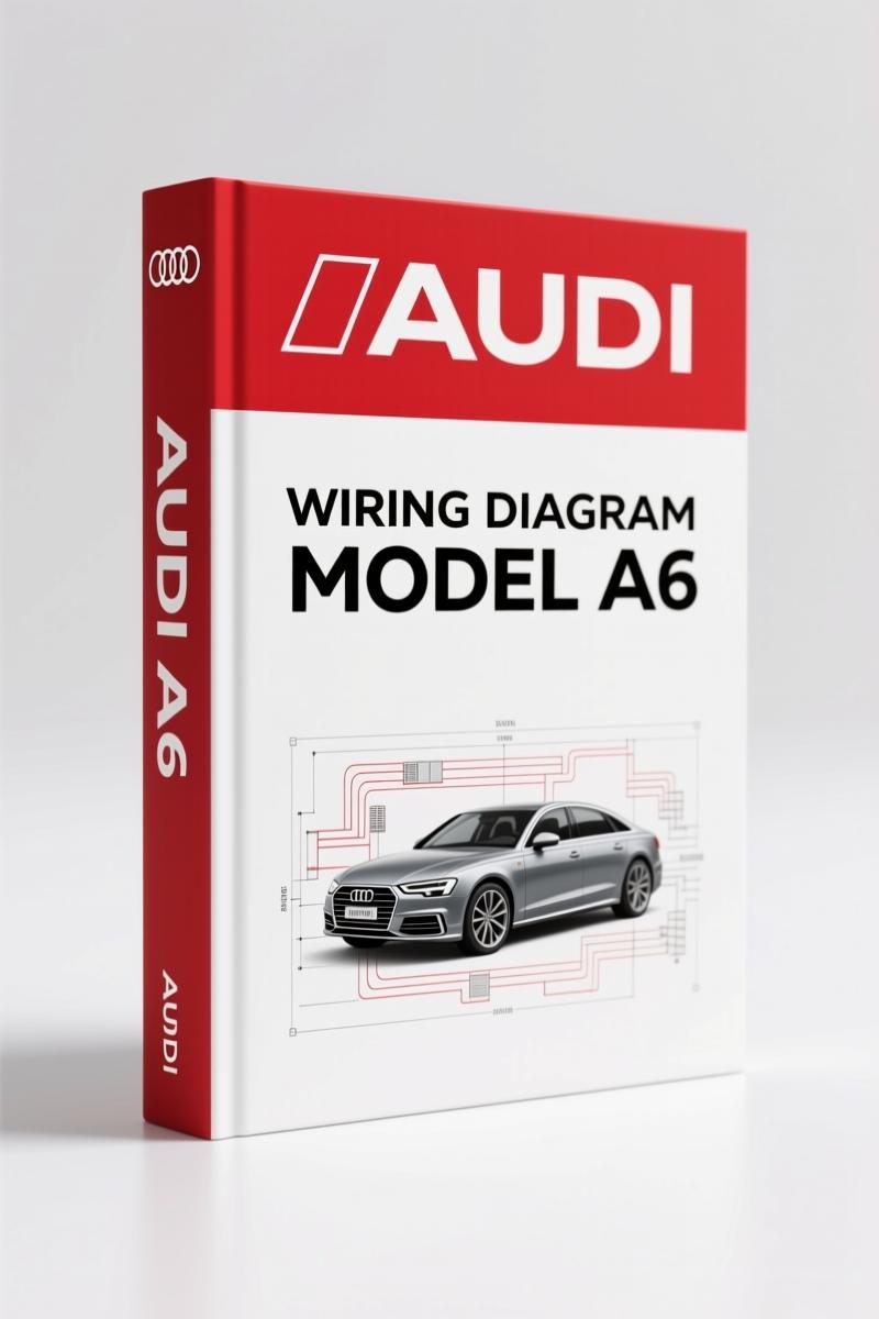
Audi A6 2001 Wiring Diagram – 74 Pages of Factory Electrical Schematics
Original price was: $22.80.$15.00Current price is: $15.00.
Factory wiring diagrams for 2001 Audi A6: instrument cluster, Motronic ECM, ABS, A/C circuits, DLC. 74 pages.
Description
2001 Audi A6 Wiring Diagram – Factory Pin Assignments and Circuit Layouts
If you’ve ever tried to trace a dead short in a 2001 Audi A6 Wiring Diagram without a proper diagram, you know the frustration. Aftermarket copies often miss a ground path or swap a wire color – that burns time and parts. This is the original 74-page factory wiring diagram manual, the same one dealer techs use. It gives you every connector view, every wire color code, and the exact pin numbers for the ECM, ABS, A/C system, and more. Don’t waste a Saturday chasing a phantom draw. Get the factory version.
Automatic A/C Circuit – Page 2 Shows the Coolant Fan Control Module
The OCR from this document shows the A/C circuit with and without the coolant fan control module (FC). Page 2 covers the full schematic for the automatic A/C with the FC module. You get wire colors like GRN/YEL for the A/C clutch relay, solid-state relay positions, and the connector at the lower left of the A-pillar (ground 6900). Do not trust a generic diagram for this – the fan control module on the 2.7L and 2.8L engines uses a specific logic that aftermarket manuals get wrong. For earlier model years, check the Audi A6 1998 Wiring Diagram to see the differences in the A/C circuit design.
Pin Assignments and Wire Colors – Don’t Probe Blind
Each connector in the 2001 Audi A6 is labeled with pin numbers and wire color abbreviations such as A1 GRN, A2 GRN/BLU, B1 BRN/BLU. The manual shows exactly which pins route to the instrument cluster, the Motronic ECM, the ABS control module, and the data link connector. If you are swapping a cluster or diagnosing a no-start condition, you need this level of detail. I have seen techs fry a module because they guessed a pinout based on a different year. This manual eliminates that risk. For more on Automotive Wiring fundamentals, read up on proper probe techniques before you start.
3 Systems Covered in This 74-Page Manual
- Motronic Engine Control Module (ECM) – Pin assignments for ignition, fuel injection, and data link connector.
- Anti-Lock Brakes System (ABS) – Control module inputs/outputs and wheel speed sensor circuits.
- Automatic A/C System – Both versions (with and without coolant fan control module), including after-run coolant pump wiring.
- Instrument cluster, wiper/washer system, interior lights, defogger, and more.
If you need the 2000 model specs, the Audi A6 2000 Wiring Diagram covers that year. For suspension and running gear training, refer to the Audi A6 2005 Running Gear Training Manual.
Source Authenticity – What You Are Getting
This is a reprint of the Mitchell factory wiring diagram set – not a scanned aftermarket hack. Mitchell is the same data used by dealer networks. Each page carries the Mitchell copyright and date stamp (2005). The document is clean, readable, and every line matches the factory. Aftermarket wiring charts often omit the solid-state relay numbering or use wrong pin abbreviations. This manual does not. For a broader understanding of Automotive Wiring standards, cross-reference with official SAE guidelines.
ECM Pinout – Page 1 Coverage
The Motronic ECM pin assignments are on page 1. You will see signals like BLK/YEL (ignition), BLK/GRY, and BLK/RED. The data link connector (DLC) partial view shows which pins carry CAN bus lines. If you are diagnosing a misfire or fuel trim issue, having the factory ECM pinout saves hours of back-probing. The manual also notes exceptions like “EXCEPT 2.8L W/ FRONT WHEEL DRIVE” – pay attention to those notes.
- Can I use this manual to install an aftermarket stereo?
- No. This covers factory systems only. For stereo wiring, you need the radio pinout supplement, not a full wiring diagram.
- What pages cover the A/C system?
- Pages 1-4 include two versions of the A/C circuit – one with coolant fan control module (pages 1-2) and one without (pages 3-4). The diagrams also show the A/C clutch relay, the solid-state relay, and the after-run coolant pump. If your car has the 2.7L or 2.8L engine, pay attention to the “EXCEPT 2.8L W/ FRONT WHEEL DRIVE” notes. The manual uses standard wire color abbreviations – for example, GRN/BLU means green with a blue stripe. Always verify the color code against your actual wiring because some wires fade over time. Also, note the ground locations like G900 on the lower left part of the A-pillar. Ground location is critical for A/C function. The coolant fan control module (FC) is a solid-state relay that relies on correct input from the thermal switch and after-run pump circuit. If you skip the factory diagram and guess the pinout, you risk damaging the FC module or the A/C compressor relay. Use the page references to find each component – the manual includes connector face views that show cavity numbers and wire entry points. That level of detail is what separates a factory document from a generic schematic.
Access the Factory Manual and keep it on your bench. Stop guessing wire colors – get the exact OEM spec that matches your 2001 Audi A6.
Additional information
| Brand | Audi |
|---|---|
| Language | English |
2 reviews for Audi A6 2001 Wiring Diagram – 74 Pages of Factory Electrical Schematics
You may also like…
-
Sale!

Audi A3 2003 Repair Manual – Fuel System Service Documentation
Original price was: $63.45.$45.00Current price is: $45.00. -
Sale!
Audi 5000 S 1985 Wiring Diagram – OEM Cooling Fan Circuit Data
Original price was: $86.90.$55.00Current price is: $55.00. -
Sale!

Audi 100, 200 1989 Workshop Manual – Factory Service for 5-Cylinder Engine
Original price was: $63.45.$45.00Current price is: $45.00. -
Sale!

Audi A8, Q7 Training Manual – Ceramic Brake Systems
Original price was: $54.00.$45.00Current price is: $45.00.
Related products
-
Sale!

1993 Operators Manual – International Bus 1000-3000 OEM Specs
Original price was: $12.30.$7.99Current price is: $7.99. -
Sale!

2006 Service Manual – International DT 466E, 530E Diesel Engine
Original price was: $67.50.$50.00Current price is: $50.00. -
Sale!
1993 Electrical Schematic – International 1000/3000/4000 Bus Chassis OEM Wiring Diagrams
Original price was: $29.26.$22.00Current price is: $22.00. -
Sale!
1994 Troubleshooting Manual – International 1000-4000 FBC
Original price was: $60.00.$50.00Current price is: $50.00.
Robert M. –
I am very pleased with this purchase. Instant access after checkout process. It assisted me to rebuild my Audi A6 engine. Highly recommended for mechanics.
diy_master –
This is just what I needed. The scan is high-quality and easy to navigate. Contains clear bolt torque specs for Audi. Worth every penny.