
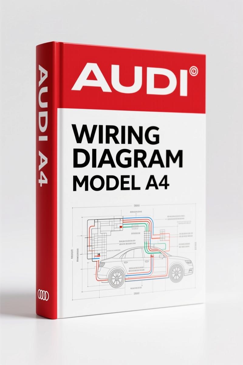
Audi A4 2001 Wiring Diagram – Factory Circuit Schematics for Technicians
Original price was: $27.80.$20.00Current price is: $20.00.
Factory wiring diagram for Audi A4 2001: 21 pages of circuit paths, ground connections, and connector layouts. Precise factory data for diagnostics.
Description
Audi A4 2001 Wiring Diagram – Factory Electrical Schematics
I’ve seen more than one guy chase an electrical ghost for three billable hours because he used a generic diagram that had the wrong pinout. That’s not a problem you get with the Audi A4 2001 Wiring Diagram. This 21-page document is the exact OEM wiring schematic Audi put together for the 2001 model year. No aftermarket shorthand, no redrawn circuits that lose a ground path. If you need to trace a short, find a relay, or figure out why the load reduction relay kills your horn, this is the paper trail that works.
What Makes This Wiring Diagram Different
Most aftermarket wiring books get lazy with the ground locations. They’ll list “ground, somewhere near left strut.” That’s useless when you’re staring at a bundle of black wires. This factory diagram gives you specific ground connection labels like “44 – Ground connection (lower left A-pillar)” and “78 – Ground connection (lower right B-pillar).” You can see those on page 3. The relay carrier layouts are drawn to scale with pin numbers. That 4-Pin Relay Carrier with threaded connection? It’s mapped out with positions E, F, G, H. You can cross-reference against the fuse chart on page 2. The fuse colors are spelled out: 15A blue, 25A white, 30A green. No guessing which orange stripe means 5A versus 7.5A.
21 Pages of Factory Schematics
21 pages sounds thin until you realize each page is a dense schematic with multiple circuits. Page 1 covers the main fuse and connector station in the plenum chamber. Page 5 hits the horn relay and load reduction relay wiring. The manual splits circuits by standard equipment from the 2002 model year—this diagram actually covers a production range that includes late 2001 builds. You get ground strap location (engine to body), color codes for wire insulation (ws = white, sw = black, ro = red, br = brown, gn = green, bl = blue, gr = grey, li = lilac, ge = yellow, or = orange, rs = pink), and connector views like T4k (4-pin, black, near front bumper). Everything a pro needs to isolate an open circuit without cutting into harnesses blind.
Are the Fuse Locations and Relay Carriers Covered?
Yes, and they’re not buried in vague text. Page 2 shows the fuse holder layout with 44 positions, including the reserved spots (Res) and the numbering shift—position 23 onwards are numbered 223 in the current flow diagram. The 9-Pin Relay Carrier in the instrument panel has a dedicated diagram. Relay 3 is the horn relay, relay 6 is the load reduction relay. That’s stuff you can’t get from a Chilton’s. If you’re chasing a no-start because the load reduction relay drops power to the ECU during crank, this diagram tells you exactly which pins to test. Pair it with the Audi A4 2001 Technical Features Manual for engine control specs, and you’ve got a full diagnostic setup.
Ground Connections: Why You Need the Exact Locations
Bad grounds cause half the intermittent electrical problems I see on this generation of the A4. The manual lists 13 distinct ground points with identifiers like “179 – Ground connection, in left headlight wiring harness” and “345 – Ground connection (in bumper wiring harness), Fanfare/Fog light.” If you’re replacing a headlight harness, you need to know ground 179 exists. If you’re installing fog lights, ground 345 is your friend. These aren’t generic “attach to body” notes—they’re specific to harness sub-bundles. For older wiring diagrams, check the Audi A4 1996 Wiring Diagram to see how the ground scheme changed. The 2001 version added a heated spray jet ground (261) that earlier years lack.
Get the Right Color Codes and Terminal Assignments
The wire colors listed on page 3 are the actual Audi factory codes. You’ll see a line like “0,35 gr/ge” meaning 0.35 mm² gray with yellow stripe. That’s the wire gauge and color. Combine that with the connector views—like T10c (10-pin, violet, connector station A-pillar, left)—and you can reconstruct any branch circuit. This is the same info Audi techs used when the car was under warranty. Don’t rely on a photocopy from an aftermarket database that lost the color key. This is the real thing. For more extensive repair contexts, grab the Audi A4, A4 Avant 2004 Repair Manual – Factory Specs & Torque Data—that one covers mechanicals, but the wiring stays similar across the platform. And if you’re new to reading schematics, read up on Automotive Wiring fundamentals to interpret the current flow diagrams correctly. Another good resource is Automotive Wiring guidelines from industry standards.
FAQ
- Does this wiring diagram cover the convertible or Avant body styles?
- The diagram is labeled for the A4 sedan and mentions the Avant in the 2004 repair manual, but this specific wiring sheet from 2001 does not differentiate between body styles. Ground locations and fuse boxes are identical across the platform for that year. If you need Avant-specific roof wiring, that’s a separate supplement.
- Can I use this for a 2002 Audi A4?
- Yes. The cover notes “from 2002 m. y.” so it covers 2002 model year cars built after August 2001.
- How do I find the pinout for the ECU connector in this manual?
- This is a body wiring diagram, not an engine management schematic. ECU pinouts are in the separate engine wiring diagram. You can cross-reference the power and ground feeds to the ECU through the relay carrier pages here.
- What if I need a printed copy instead of a digital access?
- Digital access is the only format we offer. Print it at your shop. The PDF is searchable, which beats flipping paper when you’re greasy.
You can trace a broken wire on a 2001 A4 without pulling the entire dash if you have the right schematic. Access the Factory Manual now and get the exact layout Audi put into production. One page at a time, you’ll find the short, confirm the ground, and get that electrical system behaving again.
Additional information
| Brand | Audi |
|---|---|
| Language | English |
4 reviews for Audi A4 2001 Wiring Diagram – Factory Circuit Schematics for Technicians
You may also like…
-
Sale!
Audi 5000 S 1985 Wiring Diagram – OEM Cooling Fan Circuit Data
Original price was: $86.90.$55.00Current price is: $55.00. -
Sale!

Audi 100, 200 1989 Workshop Manual – Factory Service for 5-Cylinder Engine
Original price was: $63.45.$45.00Current price is: $45.00. -
Sale!

Audi A8, Q7 Training Manual – Ceramic Brake Systems
Original price was: $54.00.$45.00Current price is: $45.00. -
Sale!

Audi A3 2003 Repair Manual – Fuel System Service Documentation
Original price was: $63.45.$45.00Current price is: $45.00.
Related products
-
Sale!

Acura NSX 1991 Service Manual – 1420 Pages OEM
Original price was: $102.05.$65.00Current price is: $65.00. -
Sale!

1994 Troubleshooting Manual – International 1000-4000 FBC
Original price was: $60.00.$50.00Current price is: $50.00. -
Sale!
1993 Operators Manual – International Bus 1000-3000 OEM Specs
Original price was: $12.30.$7.99Current price is: $7.99. -
Sale!

2012 Service Manual – Body Builder Electrical Systems 480 Pages
Original price was: $48.28.$34.00Current price is: $34.00.
workshop_guy –
I am extremely satisfied with this purchase. It is easily zoomable on my iPad without blur. A must-have for any Audi A4 mechanic doing maintenance. Saves me so much money.
Michael T. –
Perfect workshop guide. The pages are clean and well indexed. A must-have for any Audi A4 mechanic doing repairs. I will recommend this shop to others.
Thomas B. –
Perfect factory service manual. The document is high resolution. Every wiring layout is included for Audi A4. I will recommend this shop to others.
diy_master –
This is exactly what I needed. It is very easy to read on my tablet without blur. A must-have for any Audi A4 owner doing repairs. Saved my repair job! Thanks.