
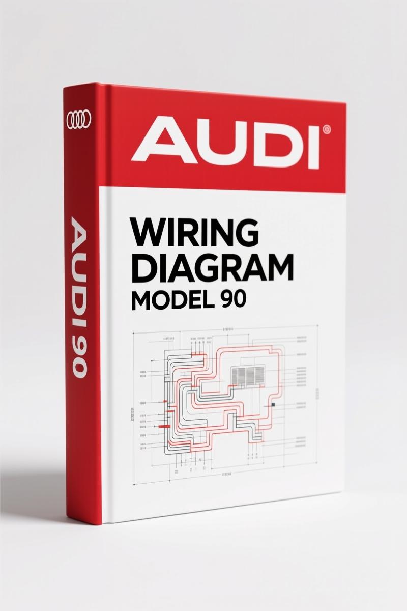
Audi 90 2005 Wiring Diagram – Factory Electrical Schematics
Original price was: $23.85.$15.00Current price is: $15.00.
Official 2005 wiring diagram for Audi 90 (1991). 19 pages: A/C, cooling fan, defogger circuits. Mitchell Reproduktion – no aftermarket guesswork.
Description
Audi 90 2005 Wiring Diagram – 19 Pages of Factory Electrical Data
If you’ve ever chased a short in an older Audi only to find the aftermarket diagram shows the wrong wire colors, you know the frustration. That’s why I keep a copy of the Audi 90 2005 Wiring Diagram on my bench. This isn’t a generic reprint – it’s 19 pages of factory Mitchell data, scanned from the original 2005 release, covering the 1991 Audi 90 system circuits. You get the same schematics the dealership techs used, with pin numbers, splice locations, and fuse ratings that are actually correct.
Air Conditioning Circuits (1 of 2 and 2 of 2)
The A/C section alone spans two full pages with separate diagrams for automatic and manual systems. The automatic A/C circuit (Fig. 1 and Fig. 2) shows the control unit, compressor relay, and high-pressure switch wiring. The manual A/C circuit (Fig. 3) is simpler but still demands correct grounding points. Page 2 details the power distribution through the fuse panel – critical if you’re swapping a blower motor or chasing a no-cold condition. Miss a wire splice and you’ll be pulling the dash twice.
Cooling Fan Circuit: Thermo Switches and Relays
Radiator fan failures are common on this generation. The cooling fan circuit (Fig. 4) shows the high-speed and low-speed relays, the after-run control unit, and the thermo switches on the radiator. Fuse 15 (25A) and Fuse 20 (30A) are hot at all times – check those first. The diagram also shows the after-run resistor and the ground points G201 and G202 behind the dash. If your fan runs constantly, the relay side of the circuit is where you start.
3 Relay Positions You Must Verify
The diagrams use a unique numbering system: relays are labeled by their panel position (e.g., A30M, D75A). The cooling fan high-speed relay, low-speed relay, and A/C relay all sit on the left side of the engine compartment fuse/relay panel. The manual identifies each relay by its terminal numbers and wire colors – red/white, red/blue, green/black. Cross-reference these with your car’s production date; early 1990 models use slightly different wiring for the after-run control.
Check the Fuse Ratings Before You Start
Safety warning: always disconnect the battery before probing these circuits. The 30A fuses can arc weld your test light to the terminal if you short against ground. Page 5 shows the fuse layout: Fuse 15 (25A) protects the cooling fan low-speed circuit; Fuse 20 (30A) handles the high-speed fan and A/C relay coil. Use only OEM-spec blade fuses – no penny tricks. The diagram also flags circuits that are hot at all times, like the cooling fan after-run resistor.
Defoggers: How the Circuit Routes Power
The defogger section is short but important. The circuit runs through a timer relay and a separate fuse. Wire colors are brown (ground), red/white, and red/blue. The ground point G202 appears again behind the left side of the dash. If your rear window defogger doesn’t work, check the relay and the fuse before condemning the grid.
Why Factory Mitchell Data Matters
Third-party wiring diagrams often merge multiple years, creating errors. This manual is a direct scan of the 2005 Mitchell release, which was compiled from Audi’s own engineering drawings. Every connector pin, wire gauge, and splice is as Audi released it. The 19 pages are organized by system, not by model year variants. You get the exact same data that a dealership tech would pull up on their Mitchell subscription.
Audience Fit: Who Needs These 19 Pages?
Home garage guys restoring a ’90 or ’91 Audi 90, and independent shops that still see these cars. The manual is not for the total beginner – you need to understand basic multimeter use and relay operation. But if you can read an electrical schematic, these diagrams will cut your diagnostic time by more than half. The wiring is specific to the 1991 Audi 90, not the later 1992-1995 cars, so buy accordingly.
- Does this manual cover the 2005 Audi 90?
- No. The manual was published in 2005 but covers the 1991 Audi 90. For a 2005 Audi 90, you need a different manual. Check our Audi A3 Wiring Diagram – OEM Fuse Box & Relay Assignments”>Audi A3 wiring diagram for newer models.
- What fuse ratings are shown?
- Fuse 15 is 25A, Fuse 20 is 30A. The manual also shows fuse 5 (30A) and fuse 17 (30A) for other circuits.
- Can I use this for a 1990 Audi 80?
- The diagrams note differences for 1990 80 models on the cooling fan circuit. Some relays and grounds are shared, but the A/C and defogger sections are specific to the 90.
- Are the wire colors accurate?
- Yes. The diagrams use factory color codes like red/white, red/blue, brown, green/red. Always verify with a multimeter because age can fade the insulation.
Access the Factory Manual and keep it on your tablet or print the pages you need. For more factory schematics, see our Audi A8 2005 Wiring Diagram – Factory OEM Specs”>Audi A8 2005 wiring diagram or the Audi allroad quattro 2005 Wiring Diagram – Factory Electrical Schematics”>Audi allroad quattro wiring diagram. If you want to understand the fundamentals of reading these diagrams, check out Automotive Wiring”>automotive wiring on Wikipedia for basic theory. For deeper electrical diagnostics, Automotive Wiring”>automotive wiring guides from SAE are a solid reference.
Additional information
| Brand | Audi |
|---|---|
| Language | English |
2 reviews for Audi 90 2005 Wiring Diagram – Factory Electrical Schematics
You may also like…
-
Sale!

Audi A3 2003 Repair Manual – Fuel System Service Documentation
Original price was: $63.45.$45.00Current price is: $45.00. -
Sale!

Audi 100, 200 1989 Workshop Manual – Factory Service for 5-Cylinder Engine
Original price was: $63.45.$45.00Current price is: $45.00. -
Sale!

Audi A8, Q7 Training Manual – Ceramic Brake Systems
Original price was: $54.00.$45.00Current price is: $45.00. -
Sale!
Audi 5000 S 1985 Wiring Diagram – OEM Cooling Fan Circuit Data
Original price was: $86.90.$55.00Current price is: $55.00.
Related products
-
Sale!

1989 Service Manual – International 2000-8000 Electrical Systems
Original price was: $72.00.$50.00Current price is: $50.00. -
Sale!

1993 Operators Manual – International Bus 1000-3000 OEM Specs
Original price was: $12.30.$7.99Current price is: $7.99. -
Sale!

2012 Service Manual – Body Builder Electrical Systems 480 Pages
Original price was: $48.28.$34.00Current price is: $34.00. -
Sale!
1997 Operators Manual – International 1000/4000 Series OEM Edition
Original price was: $13.49.$9.99Current price is: $9.99.
William H. –
This is exactly what I required. The PDF quality is excellent. A must-have for any Audi 90 DIYer doing repairs. Great value for money.
Charles W. –
I am extremely satisfied with this purchase. Instant access after payment. Every wiring layout is provided for Audi 90. Saved my repair job! Thank you.