
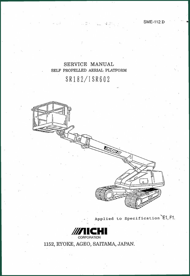
Aichi ISR602, SR182 Service Manual – 167 Page Factory OEM Document
Original price was: $39.15.$27.00Current price is: $27.00.
167-page OEM Aichi service manual for ISR602 and SR182 aerial platforms. Covers hydraulic, electric, and mechanical systems with factory torque specs.
Description
Aichi ISR602, SR182 Service Manual – Factory OEM Specifications for Aerial Platform Repairs
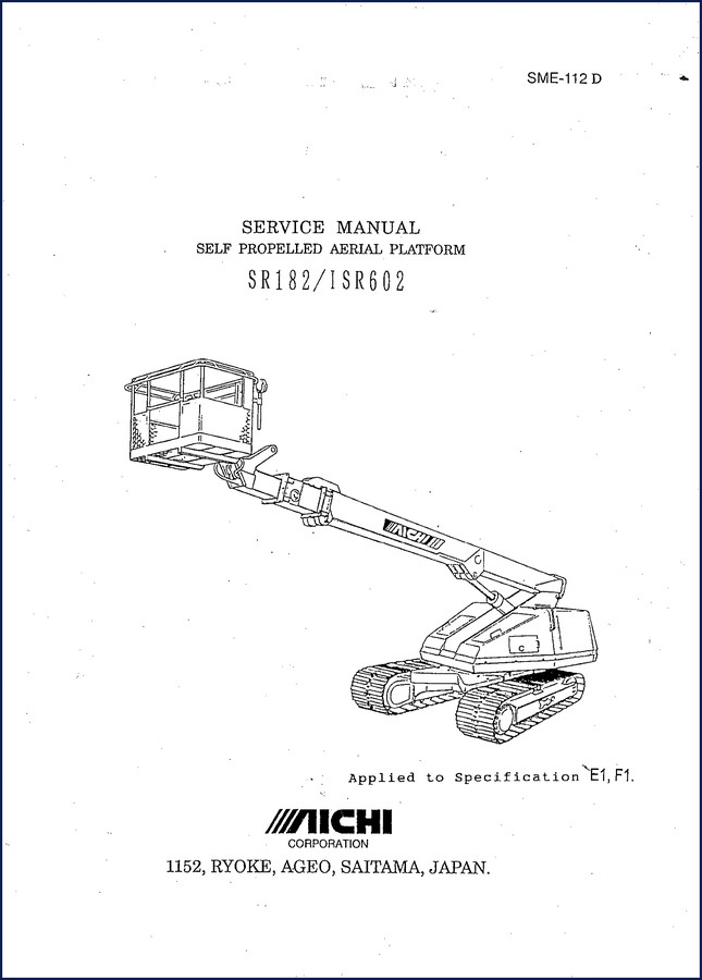
You’ve got a self-propelled aerial platform that’s dead in the yard – boom won’t lift, platform won’t level, or the hydraulics sound like a bag of bolts. The aftermarket PDF you found online has generic torque values that don’t match your machine, and the wiring diagram looks like it was drawn by a guy who’s never seen a Aichi ISR602, SR182 Service Manual. That’s the kind of frustration that costs you time and money. This 167-page factory manual from Aichi Corporation gives you the actual specs Aichi used at the factory – not a reprint, not a third-party copy, but the original document used by Aichi dealers.
Page 1-3 lists the full specifications for both models – working range, dimensions, fluid capacities. If you need the charge pressure for the hydraulic pump, it’s in section 3. The valve control unit’s input/output characteristics? Section 4, page 4-9. Every piece of data comes from Aichi’s engineering department, not some guy in a basement scanning a faded photocopy.
Boom Inspection and Wire Rope Tension
The mechanical section (section 2) breaks down the boom assembly with sectional drawings, inspection procedures, and tension specs for the extension/retraction wire ropes. You’ll find the exact procedure for adjusting the electric cable tension alongside the wire ropes. Aichi calls out inspection intervals and wear limits – use those numbers, not guesses. The turntable bearing and platform rotation mechanism are also covered here, with step-by-step inspection steps that keep the machine safe. Aftermarket manuals often skip the wire rope tension procedure because they assume you can figure it out. Don’t figure it out – use the book.
Hydraulic System Overhaul: Main Control Valves
The hydraulic section (section 3) is where most guys get stuck. Main control valve No.1 and No.2 get their own sub-sections with illustrations, sectional drawings, and a trouble-shooting guide that walks you through symptoms like ‘boom drifts down’ or ‘platform won’t rotate’. The single holding valve for the elevation cylinder and double holding valve for the extension cylinder each have separate inspection procedures – with OEM-specified test pressures and leak rates. You’ll also find the platform leveling system adjustment procedure on page 3-26, including air bleeding steps. The combination valve, priority valve, and travel speed selector valve are all covered. Every valve in the system – from the swivel joint to the AC generator solenoid valve (optional for USA) – is documented with factory part names and function notes.
Valve Control Unit: Trimmers, LEDs, and Function Notes
Electric section (section 4) dives into the control electronics. The valve control unit gets seven pages of documentation – specification, input/output characteristic, external view, trimmer functions, LED functions, and two separate notes on function. If you’re diagnosing a no-movement issue and the LEDs are blinking a pattern you don’t recognize, this section tells you exactly what each LED means and how the trimmers affect operational speed. The upper and lower control box circuits are drawn out with component IDs. Lever potentiometer, interface boards for Spec.E1 and Spec.F1, accelerator motor, tilt sensor, foot switch – all original factory wiring diagrams. No guessing which wire goes where.
Does the Adjustment Section Cover All Relief Valve Settings?
Yes. Section 6 is the adjustment section. It covers relief valve P1, P2, P3, and P4 with specific pressure settings. Operational speed measurement and adjustment procedures include the trimmer identification on the valve control unit. An adjustment data sheet gives you a place to record the final settings after you’re done. The appendix (section 7) includes a troubleshooting guide, identification of control devices and fuses, hydraulic circuit diagram, electric circuit diagram, and the tightening torque standard. That torque table is the one Aichi uses for all fasteners – use it and you won’t strip threads or under-torque safety-critical bolts.
3 Reasons to Rely on Factory OEM Over Aftermarket
First, the wiring diagrams. Aftermarket manuals redraw them and often miss a splice or a ground point. This manual has the exact Aichi electric circuit diagrams for every system – engine control, rotation (E1 and F1), extension, elevation, travel, accelerator, platform level, tilt warning, motion alarm, emergency pump, and the AC generator option. Second, the torque values. The tightening torque standard in the appendix is taken from Aichi’s own engineering standard, not a generic chart. Third, the inspection manual (section 8) gives you daily and periodic inspection check sheets. If you’re running a rental fleet or a service shop, those check sheets are the difference between a safe machine and a liability lawsuit. Check out the related AICHI SR-182/ISR602 Parts List to complement this manual with exact part numbers.
For other Aichi models, see the Aichi SR18AJ, SR21AJ, SR18A, SR21A, ISR60J Service Manual and the Aichi SR123J, ISR403J Service Manual – Factory OEM Documentation. The procedures in these manuals follow the same factory-level documentation standard.
FAQ
- Does this manual cover the Komatsu engine section that appears in the table of contents?
- Yes. Section 9 is dedicated to the Komatsu shop manual – structure, disassembly and assembly, maintenance standard. This is the engine-specific section, so you get both the Aichi platform manual and the engine manual in one 167-page document.
- What hydraulic components are listed with inspection procedures?
- Single and double holding valves, combination valve, double pilot check valves (for upper leveling cylinder and platform leveling system), travel speed selector valve, and the AC generator solenoid valve. Each procedure includes the factory test method – not a generic ‘check for leaks’ – with specific pressure and flow criteria. The platform leveling system adjustment includes air bleeding steps because air in that circuit makes the platform drift. That’s the kind of detail you don’t get from a third-party manual.
This manual is a factory original from Aichi Corporation, printed for the SR182 and ISR602 models. If you’re working on a Manual Transmission or something else, this isn’t your book. But if you need to repair or maintain an Aichi self-propelled aerial platform, this is the exact documentation used by Aichi-trained technicians. Page 2 of the manual states: ‘Use only the spare parts approved by the manufacturer, particularly for load-supporting and safety-related components.’ Follow that advice. Access the Factory Manual and get the job done with the right data.
Additional information
| Brand | Aichi |
|---|---|
| Language | English |
4 reviews for Aichi ISR602, SR182 Service Manual – 167 Page Factory OEM Document
You may also like…
-
Sale!
Aichi SR123J, ISR403J Service Manual – 146 Pages of Factory Specs
Original price was: $42.60.$30.00Current price is: $30.00. -
Sale!
Aichi SR-123, IS-R403 Service Manual – 168 Pages OEM Factory Diagnostics
Original price was: $38.40.$30.00Current price is: $30.00. -
Sale!
Aichi SP12C, SP14CJ, SP400C, SP460CJ, SP12CSM Service Manual – 173 Pages
Original price was: $42.90.$30.00Current price is: $30.00. -
Sale!
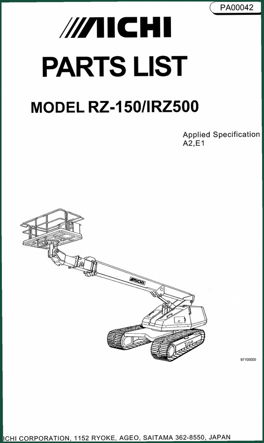
Aichi RZ-150, IRZ500 Parts Catalog – 169 Pages OEM Exploded Views
Original price was: $45.12.$32.00Current price is: $32.00.
Related products
-
Sale!

Acura NSX 1991 Service Manual – 1420 Pages OEM
Original price was: $102.05.$65.00Current price is: $65.00. -
Sale!

1991 Operators Manual – International Truck OEM Specs (108 Pages)
Original price was: $13.63.$10.99Current price is: $10.99. -
Sale!

1992 Electrical Schematic – International 1000/3000/4000/2554 OEM Wiring Diagrams (132 Pages)
Original price was: $26.40.$20.00Current price is: $20.00. -
Sale!
1991 Electrical Schematic – 112-Page OEM Wiring Diagram for International 1000-3000 Series
Original price was: $22.75.$17.50Current price is: $17.50.
Michael T. –
I am very pleased with this purchase. The text is searchable and well indexed. Every torque spec is included for Aichi ISR602,. Saves me a lot of dollars.
gearhead88 –
This is just what I needed. The pages are clean and well indexed. Every torque spec is provided for Aichi ISR602,. Highly recommended for mechanics.
Thomas B. –
Highly recommended! It is easily zoomable on my tablet without losing quality. A must-have for any Aichi ISR602, mechanic doing maintenance. I will recommend this shop to others.
pro_mechanic –
Highly recommended! Quick access after payment. It helped me to fix my Aichi ISR602, transmission. I will definitely buy again.